After discovering that the MCP23017 I2C-based GPIO expander was not going to be reliable, my first thought was to try out its SPI-based equivalent, the MCP23S17. In theory the same bug affecting the MCP23017 doesn’t affect the MCP23S17, and the communication overhead would be much lower because SPI is so much faster. I ordered some of these but haven’t experimented with them yet, because my other idea showed up first: the 74HC154, a 4-to-16 decoder IC, often used for memory address bus decoding. It has 4 input pins and 16 output pins; you set a 4-bit number (0-15) on the input pins, and it grounds the corresponding output pin while the rest remain high.
I really liked the idea of this chip not needing any communication protocol beyond 4 GPIO pins; it would eliminate the kind of problem I was having with the I2C-based expander, and should speed up the keyboard scanning loop. When I started working with it, I had two problems. The first was just an annoyance: the previous version of the adapter was cycling through the rows (via native GPIO), grounding one at a time (and leaving the rest floating), while reading in the 16 columns. This new method would be outputting the columns and reading in the rows, so I had to rework the somewhat-optimized code to all work in the opposite direction.
The other bump I encountered was more problematic. In the previous version, every time I switched which row was being scanned, I set the selected row to output low, and set all other rows to be floating inputs. Then the columns were set to input with pullups, so they’d register as low if they were connected to the selected row, and high otherwise. The reason the non-selected rows were set to floating inputs was because if you pressed two keys at once, it might connect two rows on the same column, and I didn’t want to short out a low and high output on the row pins. But the new decoder IC doesn’t leave non-selected outputs floating; they’re set as high. After testing, I confirmed what I feared, which was that the chip really did not like having those output pins shorted out.
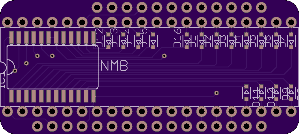
The solution in this case was kind of brute-force: 16 diodes, one per output pin of the decoder, making sure no current could ever flow out of them. It could still flow in, so I could still detect when one of the rows was connected to the selected column. The breadboard prototype for this was messy with diodes, but it worked. (Side note: fancy new mechanical keyboard with NKRO (n-key rollover) have diodes at each keyswitch to prevent ghosting of keys, but these vintage keyboards do not. Ghost avoidance will be problem for future updates.)
Anyway, here’s what the PCB design for that looks like. Now I wait for the updated boards (and surface-mount diodes) to arrive.

(I have yet to spend the time to figure out how to make my silkscreen layer not be a mess in EAGLE, but the design should work.)
