Archives

All posts for the month December, 2020

I realized that the last time I mentioned my home server, it was when I switched away from unRAID. I did so because I really wanted dual-drive redundancy, and more powerful options for running services other than basic file-sharing on it. That was some years ago, and I’ve since switched back to unRAID, because starting with version 6, it basically checks all the boxes. It now supports dual-drive parity, mirrored cache drive pools, and a very impressive collection of software add-ons made possible by docker. I’m very happy with it.

Case-wise, I think I started out using an old Antec P180 tower case, then moved things into the Norco 4U rackmount case mentioned in the older posts. It was dirt-cheap for rackmount gear, and it was just impossibly loud. You could easily hear it from another floor of my house. But it was cheap, and fit a lot of drives, and like a lot of hobbyists, all I really want is enterprise-grade hardware for cheapo prices.

After the Norco case, I moved things into the NZXT H2 tower case; I could fit 13 3.5″ hard drives into it along with a few SSDs, and it was nearly silent. I ended up making my own SATA power cables for my modular power supply to clean up the airflow inside. A nice case, but once I moved into a place where I could stash the server in the basement, I was ready for something bigger. I briefly expanded by picking up a dual external-port SAS controller card, and connecting it to a couple of 4x drive pods in an old multi-drive SCSI enclosure — you can get replacement plates for the back that swap out the old SCSI connectors with SAS, eSATA, USB, or whatever.

After doing some research online, I concluded that the cheap enterprise-grade solution I was looking for was used Supermicro gear. I really liked the look of the 933T chassis, a 3U server with 15 vertical hard drives lined up in a row. They’re all hot-swappable with a SATA backplane. (There are SCSI and SAS backplane options, but I believe the SAS version requires interposers for SATA drives, so whatever.) The 933T occasionally showed up on eBay for ~$150, often with an old Opteron-based motherboard. One nice feature of Supermicro’s hardware like this is that it’s all ATX standard, so you can swap it out for whatever else. The included power supply supported 3 redundant hotswap PSU modules, so that’s a plus.

It was pretty noisy, so I swapped out various fans (including some 40mm fans in the PSU modules, probably the noisiest of them). Now it’s nice and quiet.

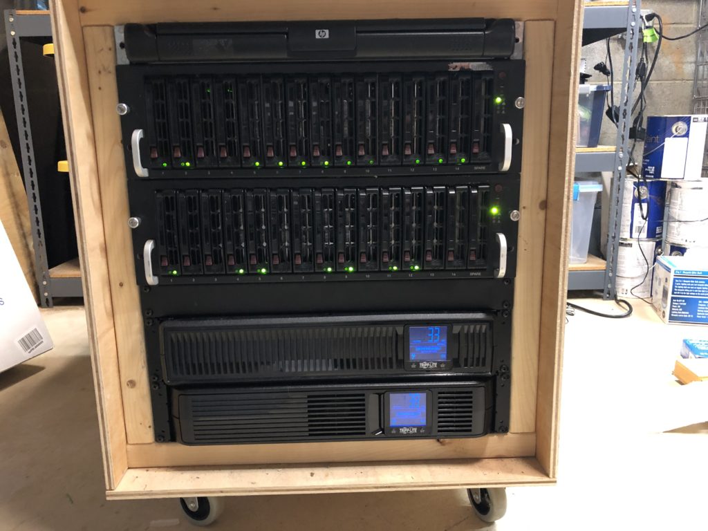
Another nice feature of Supermicro stuff is that they sell a ~$20 board designed to convert an ATX server case into a JBOD drive enclosure; it hooks up to the ATX power connector and various case connectors (power & reset button, power LED, etc.) and lets you power on/off the device without a full motherboard in it. So I bought two 933T’s! One of them contains the motherboard (an Intel DZ77GA-70k) and SAS controller, the other contains the JBOD “motherboard” and a SAS expander hooked up to the backplanes. So now I have a quiet 6U server with room for 30 hotswappable drives.

I built a simple wooden rack using some 12U brackets to put everything in, and eventually added in a couple of 2U UPS’s and an old 1U console. At some point I’d like to replace the rack with something solid (with removable panels), but otherwise I’m thrilled with the current arrangement.
After discovering that the MCP23017 I2C-based GPIO expander was not going to be reliable, my first thought was to try out its SPI-based equivalent, the MCP23S17. In theory the same bug affecting the MCP23017 doesn’t affect the MCP23S17, and the communication overhead would be much lower because SPI is so much faster. I ordered some of these but haven’t experimented with them yet, because my other idea showed up first: the 74HC154, a 4-to-16 decoder IC, often used for memory address bus decoding. It has 4 input pins and 16 output pins; you set a 4-bit number (0-15) on the input pins, and it grounds the corresponding output pin while the rest remain high.

I really liked the idea of this chip not needing any communication protocol beyond 4 GPIO pins; it would eliminate the kind of problem I was having with the I2C-based expander, and should speed up the keyboard scanning loop. When I started working with it, I had two problems. The first was just an annoyance: the previous version of the adapter was cycling through the rows (via native GPIO), grounding one at a time (and leaving the rest floating), while reading in the 16 columns. This new method would be outputting the columns and reading in the rows, so I had to rework the somewhat-optimized code to all work in the opposite direction.

The other bump I encountered was more problematic. In the previous version, every time I switched which row was being scanned, I set the selected row to output low, and set all other rows to be floating inputs. Then the columns were set to input with pullups, so they’d register as low if they were connected to the selected row, and high otherwise. The reason the non-selected rows were set to floating inputs was because if you pressed two keys at once, it might connect two rows on the same column, and I didn’t want to short out a low and high output on the row pins. But the new decoder IC doesn’t leave non-selected outputs floating; they’re set as high. After testing, I confirmed what I feared, which was that the chip really did not like having those output pins shorted out.

The solution in this case was kind of brute-force: 16 diodes, one per output pin of the decoder, making sure no current could ever flow out of them. It could still flow in, so I could still detect when one of the rows was connected to the selected column. The breadboard prototype for this was messy with diodes, but it worked. (Side note: fancy new mechanical keyboard with NKRO (n-key rollover) have diodes at each keyswitch to prevent ghosting of keys, but these vintage keyboards do not. Ghost avoidance will be problem for future updates.)

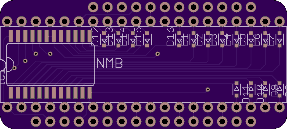
Anyway, here’s what the PCB design for that looks like. Now I wait for the updated boards (and surface-mount diodes) to arrive.

(I have yet to spend the time to figure out how to make my silkscreen layer not be a mess in EAGLE, but the design should work.)

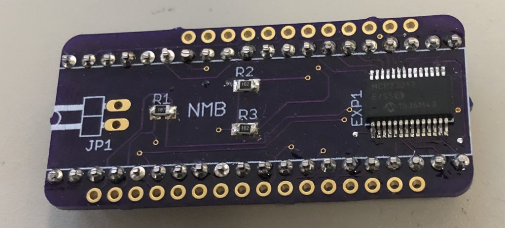
Things have been Eventful since the last post, so not a lot of time for tinkering. After discovering that the GPIO expanders I was using were too slow for handling all of the IO, I figured I had to do most of it via native GPIO pins on the microcontroller board, but I wanted a cleaner solution than I had before. So, I made this:

It’s a custom PCB with pins to interface directly with both the keyboard’s PCB (taking the place of the original 40-pin microcontroller) and the modern bluetooth controller (an Adafruit Feather nRF52832 in this case). The PCB layout for stacking onto a Feather (a “FeatherWing”) is a standard template that only had to be modified to remove some support holes to make room for the edges of the 40-pin connector.

This design uses the same I2C MCP32017 GPIO connector, and uses its 16 pins for connecting to the 16 columns of the keyboard PCB, and uses the Feather’s native GPIO pins for the 8 rows (and 3 LEDs). This way I can leave the 16 expander pins in input mode (with pullup), and cycle through the row pins on the expander for scanning the keys. Then I can read all 16 pins of the expander in one operation, to minimize the overhead. The 3 resistors on the board are for I2C pullups and the RESET line of the expander. The JP1 connector is an external connector for the ENABLE pin of the Feather board (which is also linked to the expander); this gives me an optional hookup for an external reset button if needed.

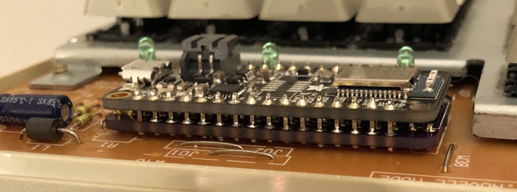
Here’s what it looks like with the Feather stacked on top, mounted on a keyboard:

Unfortunately there’s so little clearance in the keyboard case that I had to solder everything together directly; I haven’t found a removable header connector that is low-profile enough to fit. For prototyping I have one of them set up with everything socketed, but I have to use it with the top of the keyboard case removed. I really like the clean solution, though; the only wiring visible after this is the LiPo battery and a microUSB extender for charging/programming.

The only problem I had with it was that it would occasionally lock up, and require a reset. This only seemed to happen during typing, and occurred more often the more I typed. While trying to figure this out, I discovered that there was actually a design flaw in the original version of the NRF52832-based Feathers that caused them to use a lot more power than they should while in low-power mode (it was powering the USB->RS232 chip even while on battery power). I hadn’t done any power optimizations yet, but that made it kind of pointless. A newer revision of the board was available, but around that time Adafruit also released the successor to this, the NRF52840. It was faster, and had native USB support instead of requiring the RS232 converter chip. I didn’t intend to make the keyboard work as a native USB HID device, but I liked having the option. I ordered a few of those.

The other benefit of the newer NRF52840-based Feathers is that they had a preinstalled SWD debugging connector; the previous version just had the pads for it, and required you to surface-mount solder the connector. After finding that the newer Feather board periodically locked up just like the old ones, I picked up a SWD debugging interface to figure out what was going on.

Somewhat unhelpfully, the code was locking up in the same place every time, in the I2C communication library, where it waits for a response. The library doesn’t have any sort of timeouts for waiting, so it gets stuck forever. From what I’ve seen, that seems to be deliberate, as I2C devices can stretch their clock out (arbitrarily in some cases?) if they need more time to respond. Anyway, I didn’t get anywhere finding a solution to this; I considered just living with it and setting up a watchdog timer to reboot the Feather if it got stuck, but this was happening too often for that to be acceptable while typing.

I eventually found some threads online discussing a problem one user was having with the MCP32017 GPIO expander chip where he had a clock signal connected to pin 16, and the expander was occasionally giving bad responses when the level on pin 16 transitioned. In his tests, increasing the frequency of the clock signal increased how often he got corrupted responses from the chip. Other users replicated these effects, and the user reported that the manufacturer eventually confirmed that it was a bug in the chip itself, and would be addressed in a future errata publication. The official recommendation: don’t use pins 8 or 16 for input, or you will occasionally get corrupted responses.

I don’t know for sure if what I was experiencing was related to this bug, but it sure meant I was done trying to make this expander work, and ready for a new plan.