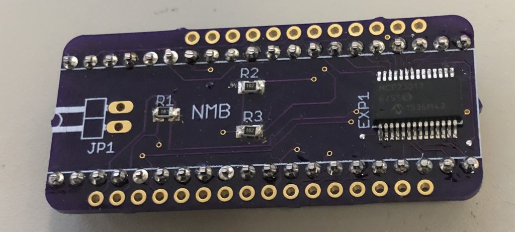
Things have been Eventful since the last post, so not a lot of time for tinkering. After discovering that the GPIO expanders I was using were too slow for handling all of the IO, I figured I had to do most of it via native GPIO pins on the microcontroller board, but I wanted a cleaner solution than I had before. So, I made this:

It’s a custom PCB with pins to interface directly with both the keyboard’s PCB (taking the place of the original 40-pin microcontroller) and the modern bluetooth controller (an Adafruit Feather nRF52832 in this case). The PCB layout for stacking onto a Feather (a “FeatherWing”) is a standard template that only had to be modified to remove some support holes to make room for the edges of the 40-pin connector.
This design uses the same I2C MCP32017 GPIO connector, and uses its 16 pins for connecting to the 16 columns of the keyboard PCB, and uses the Feather’s native GPIO pins for the 8 rows (and 3 LEDs). This way I can leave the 16 expander pins in input mode (with pullup), and cycle through the row pins on the expander for scanning the keys. Then I can read all 16 pins of the expander in one operation, to minimize the overhead. The 3 resistors on the board are for I2C pullups and the RESET line of the expander. The JP1 connector is an external connector for the ENABLE pin of the Feather board (which is also linked to the expander); this gives me an optional hookup for an external reset button if needed.
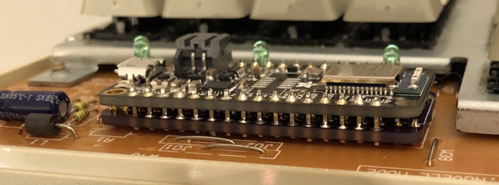
Here’s what it looks like with the Feather stacked on top, mounted on a keyboard:

Unfortunately there’s so little clearance in the keyboard case that I had to solder everything together directly; I haven’t found a removable header connector that is low-profile enough to fit. For prototyping I have one of them set up with everything socketed, but I have to use it with the top of the keyboard case removed. I really like the clean solution, though; the only wiring visible after this is the LiPo battery and a microUSB extender for charging/programming.
The only problem I had with it was that it would occasionally lock up, and require a reset. This only seemed to happen during typing, and occurred more often the more I typed. While trying to figure this out, I discovered that there was actually a design flaw in the original version of the NRF52832-based Feathers that caused them to use a lot more power than they should while in low-power mode (it was powering the USB->RS232 chip even while on battery power). I hadn’t done any power optimizations yet, but that made it kind of pointless. A newer revision of the board was available, but around that time Adafruit also released the successor to this, the NRF52840. It was faster, and had native USB support instead of requiring the RS232 converter chip. I didn’t intend to make the keyboard work as a native USB HID device, but I liked having the option. I ordered a few of those.
The other benefit of the newer NRF52840-based Feathers is that they had a preinstalled SWD debugging connector; the previous version just had the pads for it, and required you to surface-mount solder the connector. After finding that the newer Feather board periodically locked up just like the old ones, I picked up a SWD debugging interface to figure out what was going on.
Somewhat unhelpfully, the code was locking up in the same place every time, in the I2C communication library, where it waits for a response. The library doesn’t have any sort of timeouts for waiting, so it gets stuck forever. From what I’ve seen, that seems to be deliberate, as I2C devices can stretch their clock out (arbitrarily in some cases?) if they need more time to respond. Anyway, I didn’t get anywhere finding a solution to this; I considered just living with it and setting up a watchdog timer to reboot the Feather if it got stuck, but this was happening too often for that to be acceptable while typing.
I eventually found some threads online discussing a problem one user was having with the MCP32017 GPIO expander chip where he had a clock signal connected to pin 16, and the expander was occasionally giving bad responses when the level on pin 16 transitioned. In his tests, increasing the frequency of the clock signal increased how often he got corrupted responses from the chip. Other users replicated these effects, and the user reported that the manufacturer eventually confirmed that it was a bug in the chip itself, and would be addressed in a future errata publication. The official recommendation: don’t use pins 8 or 16 for input, or you will occasionally get corrupted responses.
I don’t know for sure if what I was experiencing was related to this bug, but it sure meant I was done trying to make this expander work, and ready for a new plan.
