Just a quick update here. No hardware changes since last time, but I finally got around to putting in rudimentary ghost key rejection. What I tried was laughably simple: if there are more than two new keys being detected in a single scanning pass, ignore them both and send no updates, until the next change occurs. It doesn’t even check to see if they are in positions to cause ghosting — it just relies on the fact that ghost keypresses will always appear instantaneously with the last key, and for normal keypresses that’s very unlikely. Since making that change, it’s just perfect. No ghost keypresses, and no lost keys from what I’ve noticed.
One unfortunate effect from the current decoder/diode arrangement is that I can’t really set things up for this to go to sleep and be awaked by an interrupt when any key gets pressed. So I don’t have a great way for this to go into a very low-power mode, but I can at least try to optimize the regular power usage a little. Throughout all of the previous iterations, I had a 1ms delay following each scanning pass, but the passes were now happening much faster without the IO expanders. I tried doubling the loop delay to 2ms, and noticed no change in responsiveness, but greatly increased battery life. At some point I’ll probably put something in to increase that a lot (like 25ms or so) if there haven’t been any keys pressed in an hour or so, and that’ll presumably make another huge difference. But for right now everything’s great.
Oh, I should also put in some kind of support for volume/media control. That would be useful.
So a couple of days ago I noticed that a cryptocurrency/NFT startup was using Blocks from Hell on their site (along with other unlicensed games) as part of a thing they push as “Get Paid to Play Games!”. In reality you have to front some amount of currency to play games, and while you play they pool it together and use it to mine new currency via Proof-of-Stake, and kick back some scaled percentage to you. So it’s less “get paid to play games” and more “a weird savings account that only accrues interest when you are actively playing Minesweeper, from a non-bank that is not regulated or insured”. I can see why they went with their description. The games, of course, serve no real purpose beyond marketing gimmick and psychological hook.
I am amused by the hypocrisy involved in people who are selling NFTs from a website built by copying a bunch of games without any permission or licensing. Not surprised, but amused.
Anyway, for any future cases like this, I am not interested. For the current site, I asked them to remove the game and they have promised to take it down in the next couple of weeks.
Now that I’m partly back in my office, I had to have two functioning keyboards again. I dusted off the two latest-version modified NMB keyboards, and tweaked the debounce timing on them slightly, and they’re working fine as my daily drivers. The current debounce logic is very rudimentary; between each loop through scanning the keyboard matrix, the firmware delays by 1ms. If there was a change in key state, this is sent over bluetooth, and the firmware delays by DEBOUNCE_DELAY (currently 20ms) before scanning again. If I were super picky, I’d just ignore bounces in the most recently-changed key, but for real-world typing this seems fine. Any time I get spurious key repeats, I can either clean the switch contacts or increase the delay value.
I do need to implement some kind of anti-ghosting mechanism, since the old keyboards have no NKRO diodes or anything; if I’m sloppy while typing, I’ll easily start getting ghost keypresses. My plan for a rudimentary solution for that is that if there’s ever a key-scanning update that results in two keypresses being added in the same millisecond, then ignore that update until the state changes again. Most of the cases where I’m getting ghost keypresses are when I’m pressing three keys in sequence but I’m late in releasing the earlier keys, so I get events for key1, key2, and then key3+ghost_key. (This happens when two of the keys being pressed share a row, and two of the keys being pressed share a column, and the end result basically shorts out another intersection on the key matrix. So if the keys being pressed are at A1, B1, and A2, when the third key is pressed it will also appear that B2 is pressed, because row 2 and column B are connected through the other three keyswitches.) Anyway, since I don’t know which of the two simultaneous keys being detected is real, I can just ignore both of them, and once one of the first two keys is released the situation should be resolved and the next update can go through.
One of the keyboards is the large Windows-key-equipped version, with everything mounted internally. The other one is one of the smaller 101-key models, and the bluetooth board is mounted on top, in a socket, too tall to fit inside the case. I finally got tired of using it with the top part of the case removed, so I just cut a hole out of the top to accommodate it. Much nicer.
As of the last update, I had a nice setup with a couple of Supermicro cases; one used as a SAS JBOD box, and one containing a consumer Intel motherboard. I happened upon a good deal on another Supermicro server, this time in a 2U case with 24 hotswap 2.5″ SAS bays (connected to an expander) dual 1200W PSUs, and an X8DTH motherboard with two Xeon E5645 CPUs, 64GB of ECC RAM, a built-in LSI SAS HBA, and IPMI with remote KVM. I was just shopping around for a motherboard, and for the price the case was just a bonus.
I started out by moving the new motherboard into one of the 3U cases; I wasn’t sure I was going to use the 2U case at all, and the 3U case would let me use full-height cards in the 7(!) PCIe x8 slots in the new board. That setup was really unstable, though, and eventually I came to the conclusion that the PSUs in the 3U cases just weren’t up to the task.
So, I moved the board back to the 2U case and used both 3U cases as SAS JBOD boxes. I had to pick up a replacement GPU to fit the half-height slots of the 2U case, but the new setup is rock-solid. The end result has 54 drive bays, 24 threads, and 96GB of RAM. The 2U case has passive heatsinks on the Xeons, and uses midplane fans with ducting to cool everything. The stock fans were super loud, but replacing them with Noctua fans didn’t provide sufficient cooling. I ended up putting the stock fans back in and fiddling with a script to slow down the stock fans via SMBus. It’s not as quiet as I’d like, but it’s quiet enough. I replaced the home-built rack with a metal-frame one, albeit without sides or a top. Cable management is definitely a lot easier.
Success! I got the latest PCBs over the holidays, and finally had a chance to assemble a couple of them. Using the new decoder chip instead of the i2c GPIO expander is way faster. Faster enough that for the first time in this project, I had to worry about putting in a debouncing delay. (Keyswitches like these “stutter” a bit when closing or opening, so if you’re fast enough at scanning them, you’ll get repeated presses.) The loop that scans through the rows/columns has a 1ms delay at the end, so I just added an additional delay any time the key state changed, and adjusted that until things seemed stable (around 10ms). At that point most of the keys were fine, but a few of them sporadically stuttered. I popped the keycaps off and cleaned the switch contacts with sandpaper, and now they’re fine. (One nice feature of the NMB/Hi-Tek “space invaders” keyswitches is that you can do this without disassembling everything.)
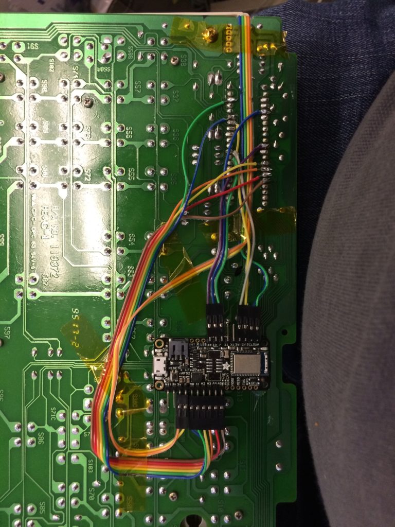
The PCB I made stacks onto the Adafruit Feather microcontroller board, and then attaches to the keyboard PCB. For testing purposes, I have all of these things socketed, but at that point the whole mess sticks up enough that the top of the keyboard frame won’t fit. I haven’t found detachable connectors that were low-profile enough to fit, so for actual deployment I’m soldering everything down pretty much flat. Here’s the Feather and adapter board soldered together, and stuck into a testing socket:
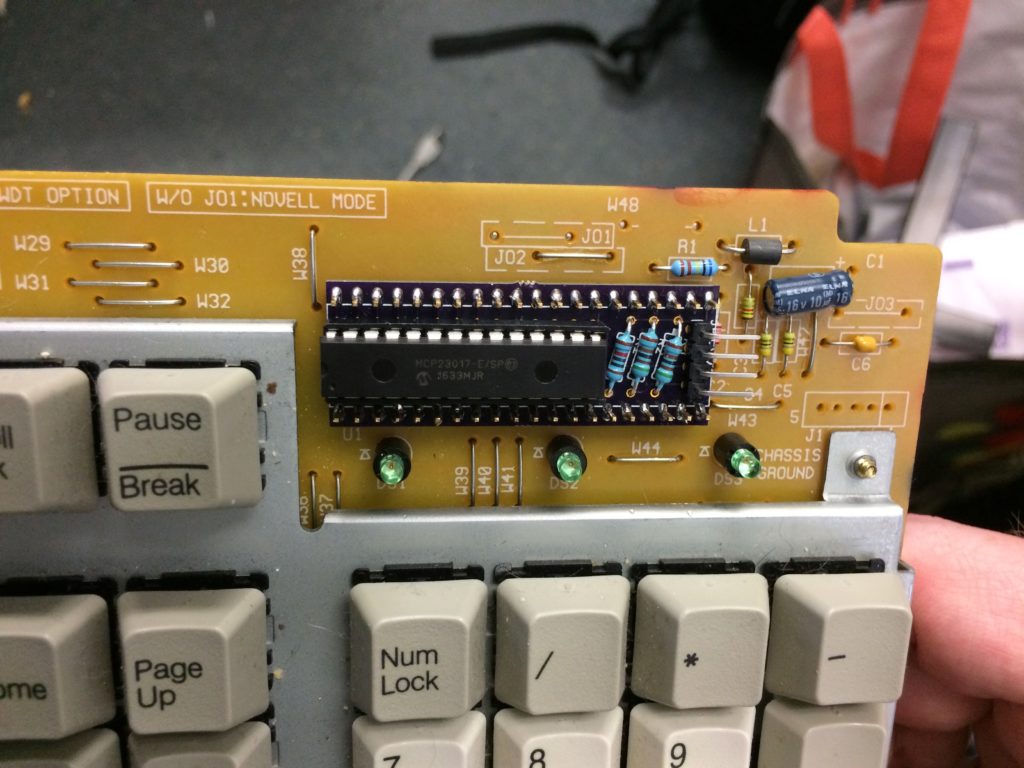
In fact, there are two general models of keyboard that I’m working with; that one is the more compact layout (the RT8756C+ and similar). It predates the existence of the Windows modifier keys. The other models are the RT8255C+ and RT8255CW+, the latter of which is the only one of these keyboards I’m aware of that includes the Windows key. These models have a larger, flatter case, and they have no space on top for the adapter. They do have a bit of space underneath, though. On the wrong side of the PCB. So, for those it’s a bit of a hack. Here’s the top side:
In place of the original 40-pin microcontroller, there’s just some header pins, pushed all the way down so they stick on the other side enough that I can solder them in place and then still stick a connector onto them, like so:
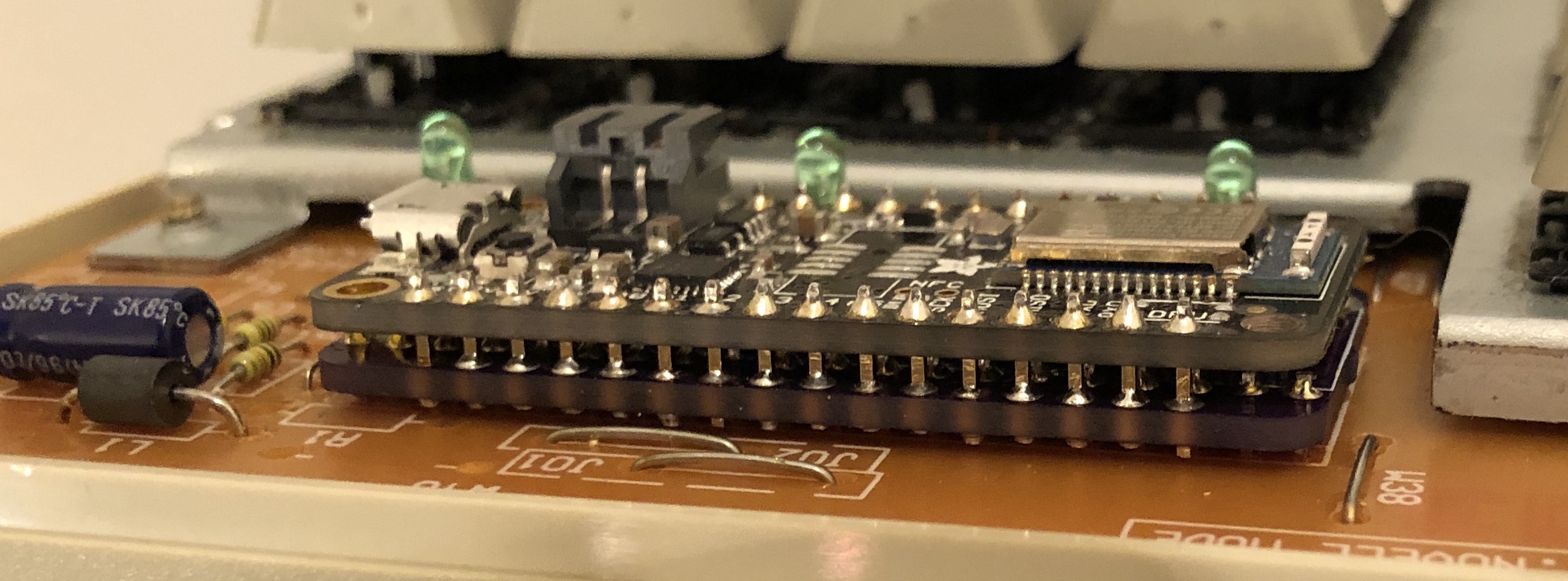
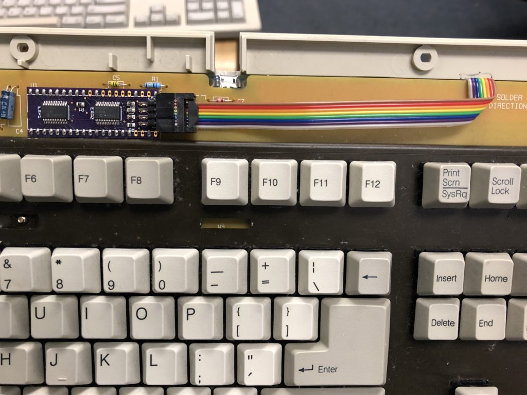
That’s the same Feather/adapter combo as before, but assembled upside-down, with a 40-pin socket soldered to the adapter so it can connect with the pins hanging down from the keyboard PCB:
I had to trim the socket to fit around the decoder chip, but it all fits, and works. Here’s what it looks like installed:
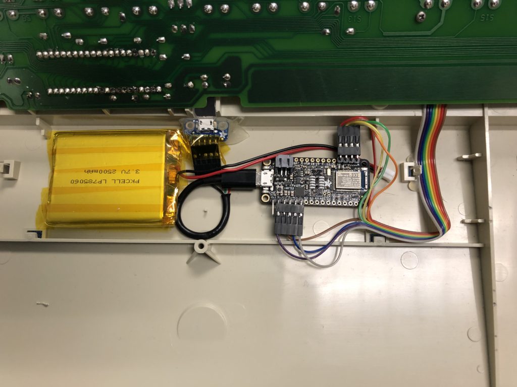
It’s a pretty minimal installation; just the adapter/Feather combo, a Li-Poly battery, and a microUSB extension leading to the outside, so it can be plugged in for charging and reprogramming.
Now that the keyboard is functional, I’ve been able to start going through the rest of the to-do list for features. First up was making the capslock light work. I could make the NumLock and Scroll Lock lights work, but nothing really uses them. One of the to-do items is to repurpose the Scroll Lock light as a battery indicator (flash slowly at 50%, quickly at 10%). I need to put in some ability to have a hotkey for “Consumer Control” keys like volume up/down and playback control. I don’t know how long this battery lasts with the current arrangement, but I may want to put in some sort of sleep mode. Unfortunately, one drawback of the current arrangement with the decoder chip is that there’s no way to select all columns at once so I can have the microcontroller go into sleep mode until any key at all gets hit and generates an interrupt. I may be able to rework the design to add in transistor logic to accomplish that, but it would undoubtedly be more complex. Worst-case, I can designate a special “wake key” that is the only one that would wake up the keyboard and just monitor that one.
I also need to come up with a good solution for filtering out ghosted keys; since keyboards like this work by connecting rows and columns of connections, if you press some arrangements of keys, they’ll short out and make it look like an additional key is pressed. If you press the keys in position A1 and A4, and then press the key in the C1 position, it will also appear that you pressed the C4 key; column C and row 4 are connected because C and 1 are connected, and 1 and 4 are both connected together through A. Newer keyboards that support effectively unlimited simultaneous keypresses (NKRO, or N-key rollover) work by having a diode inline with each keyswitch, preventing it from shorting out backwards like that. These keyboards don’t have any of that. My plan for this so far is to take advantage of the fact that when a ghosted key appears, it should always be two new keys being detected in the same scanning pass, which is unlikely to happen otherwise. So if it sees two new keys being pressed, it should just ignore them until the next key state change occurs.
Anyway, unless I think of a clever arrangement for supporting interrupt-driven wakeup, the hardware side might be done.
I realized that the last time I mentioned my home server, it was when I switched away from unRAID. I did so because I really wanted dual-drive redundancy, and more powerful options for running services other than basic file-sharing on it. That was some years ago, and I’ve since switched back to unRAID, because starting with version 6, it basically checks all the boxes. It now supports dual-drive parity, mirrored cache drive pools, and a very impressive collection of software add-ons made possible by docker. I’m very happy with it.
Case-wise, I think I started out using an old Antec P180 tower case, then moved things into the Norco 4U rackmount case mentioned in the older posts. It was dirt-cheap for rackmount gear, and it was just impossibly loud. You could easily hear it from another floor of my house. But it was cheap, and fit a lot of drives, and like a lot of hobbyists, all I really want is enterprise-grade hardware for cheapo prices.
After the Norco case, I moved things into the NZXT H2 tower case; I could fit 13 3.5″ hard drives into it along with a few SSDs, and it was nearly silent. I ended up making my own SATA power cables for my modular power supply to clean up the airflow inside. A nice case, but once I moved into a place where I could stash the server in the basement, I was ready for something bigger. I briefly expanded by picking up a dual external-port SAS controller card, and connecting it to a couple of 4x drive pods in an old multi-drive SCSI enclosure — you can get replacement plates for the back that swap out the old SCSI connectors with SAS, eSATA, USB, or whatever.
After doing some research online, I concluded that the cheap enterprise-grade solution I was looking for was used Supermicro gear. I really liked the look of the 933T chassis, a 3U server with 15 vertical hard drives lined up in a row. They’re all hot-swappable with a SATA backplane. (There are SCSI and SAS backplane options, but I believe the SAS version requires interposers for SATA drives, so whatever.) The 933T occasionally showed up on eBay for ~$150, often with an old Opteron-based motherboard. One nice feature of Supermicro’s hardware like this is that it’s all ATX standard, so you can swap it out for whatever else. The included power supply supported 3 redundant hotswap PSU modules, so that’s a plus.
It was pretty noisy, so I swapped out various fans (including some 40mm fans in the PSU modules, probably the noisiest of them). Now it’s nice and quiet.
Another nice feature of Supermicro stuff is that they sell a ~$20 board designed to convert an ATX server case into a JBOD drive enclosure; it hooks up to the ATX power connector and various case connectors (power & reset button, power LED, etc.) and lets you power on/off the device without a full motherboard in it. So I bought two 933T’s! One of them contains the motherboard (an Intel DZ77GA-70k) and SAS controller, the other contains the JBOD “motherboard” and a SAS expander hooked up to the backplanes. So now I have a quiet 6U server with room for 30 hotswappable drives.
I built a simple wooden rack using some 12U brackets to put everything in, and eventually added in a couple of 2U UPS’s and an old 1U console. At some point I’d like to replace the rack with something solid (with removable panels), but otherwise I’m thrilled with the current arrangement.
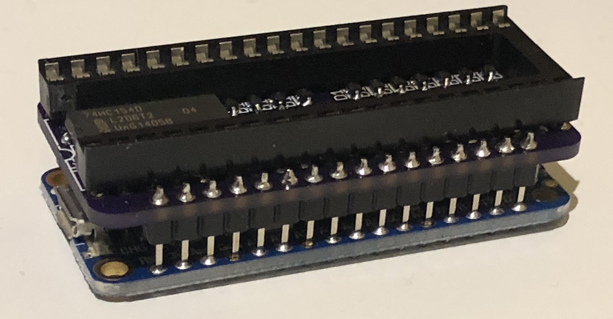
After discovering that the MCP23017 I2C-based GPIO expander was not going to be reliable, my first thought was to try out its SPI-based equivalent, the MCP23S17. In theory the same bug affecting the MCP23017 doesn’t affect the MCP23S17, and the communication overhead would be much lower because SPI is so much faster. I ordered some of these but haven’t experimented with them yet, because my other idea showed up first: the 74HC154, a 4-to-16 decoder IC, often used for memory address bus decoding. It has 4 input pins and 16 output pins; you set a 4-bit number (0-15) on the input pins, and it grounds the corresponding output pin while the rest remain high.
I really liked the idea of this chip not needing any communication protocol beyond 4 GPIO pins; it would eliminate the kind of problem I was having with the I2C-based expander, and should speed up the keyboard scanning loop. When I started working with it, I had two problems. The first was just an annoyance: the previous version of the adapter was cycling through the rows (via native GPIO), grounding one at a time (and leaving the rest floating), while reading in the 16 columns. This new method would be outputting the columns and reading in the rows, so I had to rework the somewhat-optimized code to all work in the opposite direction.
The other bump I encountered was more problematic. In the previous version, every time I switched which row was being scanned, I set the selected row to output low, and set all other rows to be floating inputs. Then the columns were set to input with pullups, so they’d register as low if they were connected to the selected row, and high otherwise. The reason the non-selected rows were set to floating inputs was because if you pressed two keys at once, it might connect two rows on the same column, and I didn’t want to short out a low and high output on the row pins. But the new decoder IC doesn’t leave non-selected outputs floating; they’re set as high. After testing, I confirmed what I feared, which was that the chip really did not like having those output pins shorted out.
The solution in this case was kind of brute-force: 16 diodes, one per output pin of the decoder, making sure no current could ever flow out of them. It could still flow in, so I could still detect when one of the rows was connected to the selected column. The breadboard prototype for this was messy with diodes, but it worked. (Side note: fancy new mechanical keyboard with NKRO (n-key rollover) have diodes at each keyswitch to prevent ghosting of keys, but these vintage keyboards do not. Ghost avoidance will be problem for future updates.)
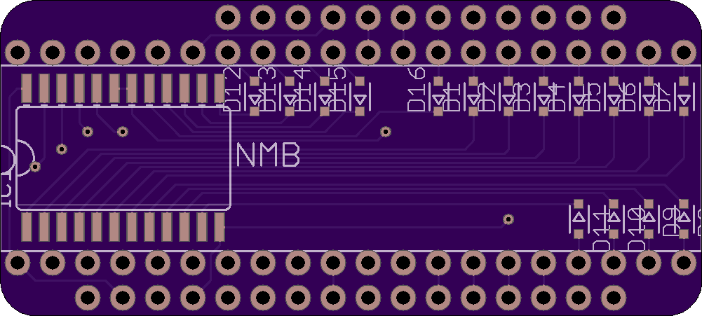
Anyway, here’s what the PCB design for that looks like. Now I wait for the updated boards (and surface-mount diodes) to arrive.
(I have yet to spend the time to figure out how to make my silkscreen layer not be a mess in EAGLE, but the design should work.)
Things have been Eventful since the last post, so not a lot of time for tinkering. After discovering that the GPIO expanders I was using were too slow for handling all of the IO, I figured I had to do most of it via native GPIO pins on the microcontroller board, but I wanted a cleaner solution than I had before. So, I made this:
It’s a custom PCB with pins to interface directly with both the keyboard’s PCB (taking the place of the original 40-pin microcontroller) and the modern bluetooth controller (an Adafruit Feather nRF52832 in this case). The PCB layout for stacking onto a Feather (a “FeatherWing”) is a standard template that only had to be modified to remove some support holes to make room for the edges of the 40-pin connector.
This design uses the same I2C MCP32017 GPIO connector, and uses its 16 pins for connecting to the 16 columns of the keyboard PCB, and uses the Feather’s native GPIO pins for the 8 rows (and 3 LEDs). This way I can leave the 16 expander pins in input mode (with pullup), and cycle through the row pins on the expander for scanning the keys. Then I can read all 16 pins of the expander in one operation, to minimize the overhead. The 3 resistors on the board are for I2C pullups and the RESET line of the expander. The JP1 connector is an external connector for the ENABLE pin of the Feather board (which is also linked to the expander); this gives me an optional hookup for an external reset button if needed.
Here’s what it looks like with the Feather stacked on top, mounted on a keyboard:
Unfortunately there’s so little clearance in the keyboard case that I had to solder everything together directly; I haven’t found a removable header connector that is low-profile enough to fit. For prototyping I have one of them set up with everything socketed, but I have to use it with the top of the keyboard case removed. I really like the clean solution, though; the only wiring visible after this is the LiPo battery and a microUSB extender for charging/programming.
The only problem I had with it was that it would occasionally lock up, and require a reset. This only seemed to happen during typing, and occurred more often the more I typed. While trying to figure this out, I discovered that there was actually a design flaw in the original version of the NRF52832-based Feathers that caused them to use a lot more power than they should while in low-power mode (it was powering the USB->RS232 chip even while on battery power). I hadn’t done any power optimizations yet, but that made it kind of pointless. A newer revision of the board was available, but around that time Adafruit also released the successor to this, the NRF52840. It was faster, and had native USB support instead of requiring the RS232 converter chip. I didn’t intend to make the keyboard work as a native USB HID device, but I liked having the option. I ordered a few of those.
The other benefit of the newer NRF52840-based Feathers is that they had a preinstalled SWD debugging connector; the previous version just had the pads for it, and required you to surface-mount solder the connector. After finding that the newer Feather board periodically locked up just like the old ones, I picked up a SWD debugging interface to figure out what was going on.
Somewhat unhelpfully, the code was locking up in the same place every time, in the I2C communication library, where it waits for a response. The library doesn’t have any sort of timeouts for waiting, so it gets stuck forever. From what I’ve seen, that seems to be deliberate, as I2C devices can stretch their clock out (arbitrarily in some cases?) if they need more time to respond. Anyway, I didn’t get anywhere finding a solution to this; I considered just living with it and setting up a watchdog timer to reboot the Feather if it got stuck, but this was happening too often for that to be acceptable while typing.
I eventually found some threads online discussing a problem one user was having with the MCP32017 GPIO expander chip where he had a clock signal connected to pin 16, and the expander was occasionally giving bad responses when the level on pin 16 transitioned. In his tests, increasing the frequency of the clock signal increased how often he got corrupted responses from the chip. Other users replicated these effects, and the user reported that the manufacturer eventually confirmed that it was a bug in the chip itself, and would be addressed in a future errata publication. The official recommendation: don’t use pins 8 or 16 for input, or you will occasionally get corrupted responses.
I don’t know for sure if what I was experiencing was related to this bug, but it sure meant I was done trying to make this expander work, and ready for a new plan.
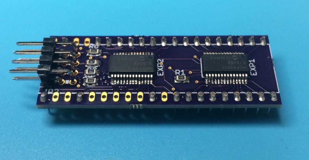
For this one I wanted to clean up the wiring to the keyboard PCB, and work towards making something that was a drop-in replacement for the original microcontroller. To this end, I bought tiny surface-mount versions of the IO expander chips, which were small enough to fit 2 on a board the size of the original microcontroller:
First surface-mount board. Looks nicer when not magnified (it’s 2″ long).
The 32 IO pins from the expanders were sufficient to connect to all of the rows and columns and LEDs. It has an 8-pin ribbon cable connector for power, ground, clock, data, and four more pins for interrupts from the expander chips. The keyboard firmware I was working with wasn’t interrupt-driven as of yet, but I wanted to have the option.
Up until this time, the pinouts I was using varied only slightly, so I had a few #defines in the code to switch between models. Since this one offloaded everything onto the expander chips, I reworked the code to be more abstracted and cleaned up.
Unfortunately, this one didn’t initially work. This turned out to be for two reasons. First, sometimes the expander chips would get into a state where the startup code wouldn’t get them working. Cycling power to everything would return them all to a known state, but that was going to be complicated once it had battery power. I considered adding a button to the bluetooth board’s Enable pin, so I could power-cycle everything even when it was closed up with a battery, but some experimentation showed the better answer was to tie the Reset pins for the bluetooth board and expanders together, so the expanders got reset every time the bluetooth board rebooted.
The other problem was that it was just too slow. The abstracted code was definitely a lot slower, but even after optimizing it, it wasn’t performing to what I needed. Hitting a key very rapidly would sometimes get missed by the matrix scanning. I had assumed the IO operations going through the expander chips would be slower than the built-in IO pins, but when I did some quick benchmarking, they appeared to be between 200 and 500 times slower. Using one expander chip for the columns was fine before, because I could leave them all as inputs, and read all 16 pins in one operation. But the rows were more problematic, because they had to be cycled through, and each time the pin had to be switched between input and output; the currently-selected row had to be set as output-low, and the non-selected rows had to be set as floating inputs, while the columns could all be set as inputs with pullups. I figured even if I set things up to be interrupt-driven, the rows would still need to be scanned through, and the tests indicated it would probably be too slow.
This was disappointing, because I liked the idea of just having the option of being able switch bluetooth microcontrollers with anything else that had i2c connectivity. If I was going to go back to just using a single expander chip for the columns, I’d have to come up with a different solution for cleaning up the wiring.
The obvious next step in cleaning up the wiring was to connect the IO expander chip directly to the keyboard PCB. Doing it with protoboard would have been a tight fit, so this was my first experience designing a custom PCB. I drew it up in EAGLE CAD, and sent if off to OSHPARK to be manufactured for ridiculously cheap. ($9 for 3, if I recall correctly).
The board held the IO expander chip, three resistors needed to make it work, and a 4-pin connector for the power/ground/clock/data lines to the bluetooth board. It cleaned up a lot of the wiring, but there was still the mess of the rows/LEDs running to the bluetooth board:
Better, but still yuck.
Once again it worked, but I knew I could do better.