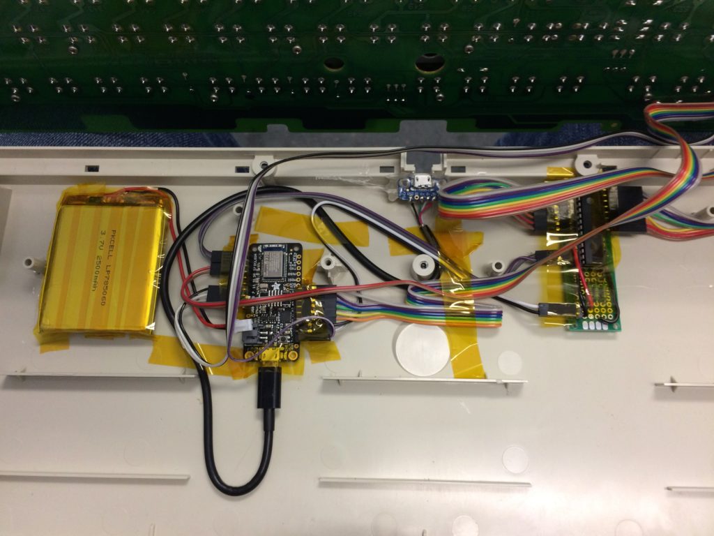
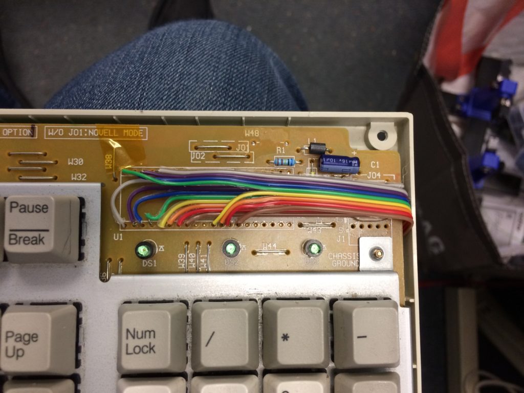
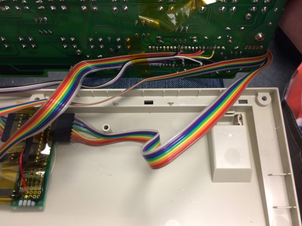
There seem to be a few different models of NMB keyboards, but they mostly boil down to some that are more wedge-shaped but have thinner bezels, and some that are flatter but have a larger bezel. I’ve only ever found one model that was new enough to have Windows keys, and it’s one of the thin ones that takes up a lot of space.
I started by mapping out the pinout of the microcontroller; I think I even found some official documentation at some point. But I ended up with a list of which pins on the 40-pin chip were rows, which were columns, which were capslock/numlock/scrolllock LEDs, and which were power and ground. The rest didn’t really matter.
The NMB keyboards have a matrix with 8 rows and 16 columns. Unfortunately, the bluetooth microcontrollers available didn’t have enough IO pins to connect directly to all of these. My solution was to pick up some IO expander chips (the MCP23017). It’s connected via i2c, so all it needs from the microcontroller is four pins (power, ground, clock, and data). It provides 16 IO pins.
The bluetooth microcontroller I picked was the (then relatively new) NRF52 Feather board from Adafruit. The first version of the board had a bug that prevented it from going into very low power mode (because it was powering the USB->serial chip off of the battery), but it was still a nice board.
For the first version of this, I put one of the expander chips on some prototype board, connected it to the bluetooth microcontroller, and then connected the expander chip to the columns, and the bluetooth board to the rows and LEDs.


This worked, but I really wasn’t happy with the mess of wires on both sides of the board. I was determined to follow it up with a version that cleaned up or eliminated a lot of the wiring.
