
Once I saw the animated lights from the Valor FX LED rings, I really wanted to see them lighting up some kind of exhaust. You can buy small battery-operated fog machines for this purpose, but I didn’t want to have to worry about potential sensitivities people might have to the special liquid used in those. I was particularly intrigued by the existence of cheap, readily-available coin-sized piezoelectric discs that used ultrasonic vibration to turn water into vapor. These get built into little humidifiers a lot, and you can get one with a driver board that runs off of 5VDC for a few bucks. I picked one up and tested it out, and it looked great. The only problems were a) it wasn’t nearly enough vapor, and b) it was designed to emit it upwards. Also I’d have to fit whatever I wanted into the space inside the LED rings, without blocking too much of the hollow channel in the middle of the engine where the sound comes out, and make it feasible to refill the water reservoir and replace the piezo discs (which are reportedly a consumable item).

As a first pass, I picked up some small watertight storage bottles that would (barely) fit in the required area, and designed & printed an enclosure to hold three of the discs in the lid. This way, the bottle could be unscrewed for filling or emptying. It would still emit the vapor upwards, but I figured I’d stick a small fan up at the top of the engine, blowing that downwards.
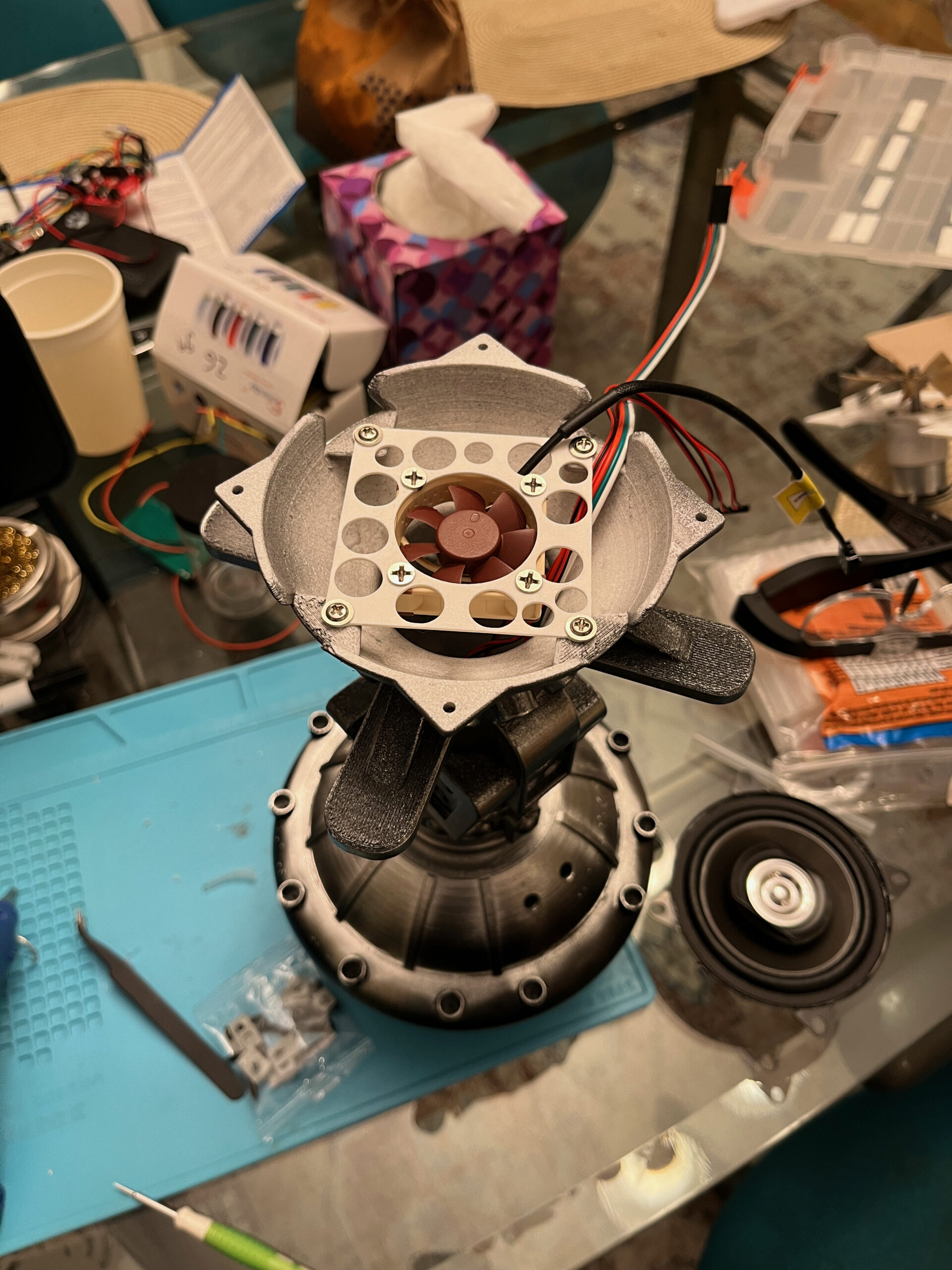
The fan options did not work. I started out with quiet little fans that could fit entirely underneath the speakers, and they didn’t move nearly enough air. I tried replacing them with larger fans that would require making a mounting bracket for the speaker, and just never got a decent result.
So, new plan: how effectively could I just mount the emitters upside down? They came with little silicone grommets, but their included plastic enclosures were definitely not designed for any non-upright arrangement. I tried designing a new enclosure for them that used some nitrile o-rings, and it seemed promising. Also the 3 emitters didn’t seem quite sufficient, so I came up with this:

This assembly held five emitters, with a tube that would lead up and out of the top of the engine, all the way to the top of the tank so it could be refilled via the nose cone openings. Some aspects of it looked good, but it just wasn’t the right answer. So I took a step back and questioned some initial assumptions.
The answer I settled on was to replace the LED rings with smaller versions of the same thing, then I could fit the exhaust emitters around the LEDs rather than in the middle of them. I found a compatible LED ring with the same number of LEDs, that was a drop-in replacement, and about as small as it could be and still fit those components. (I eventually realized I could have tried flex-cable mounted LEDs and wrapped them around the inside circumference of the engine nozzle, but this worked well.)
With the smaller LED rings, I could fit six emitters, which seemed like a good number — one of the available kits included a cheap 5VDC driver board that handled six discs at once, and I figured I could mount one of those on each engine. I still wanted them to be serviceable and easily fillable though, and designing a donut-shaped exhaust assembly seemed like it was asking for trouble.
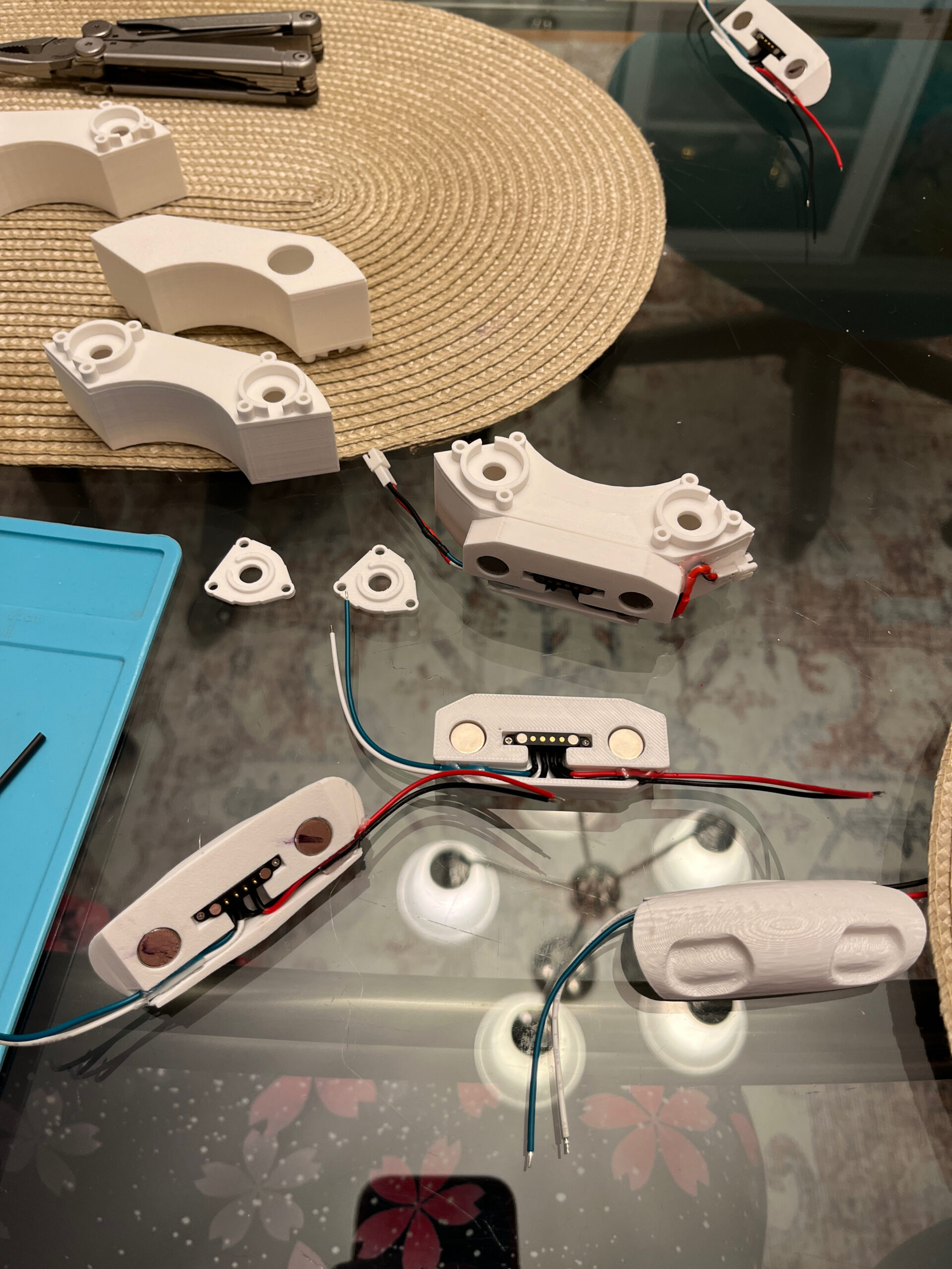
So here’s my solution: I designed separate interchangeable exhaust modules, each of which contains 2 emitters and its own little reservoir. (And a printed TPU plug you can pop out to refill or empty them.) They attach magnetically, and even have little magnetic pogo-pin connections for the electrical hookups. You can see the modules up top, and the rounded mounting points at the bottom. Here’s what it looks like with them in place on an unpainted test engine:

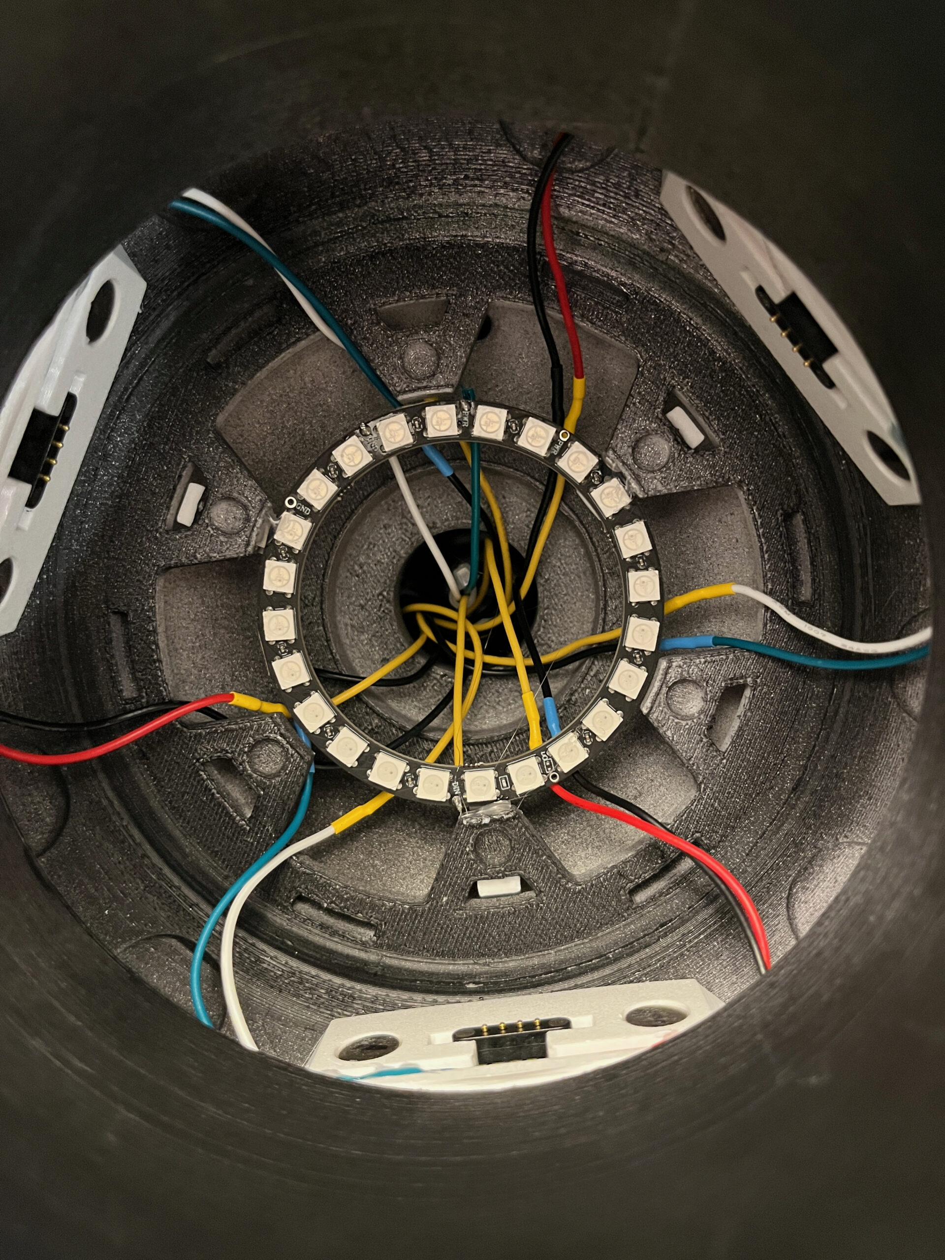
There is just barely enough room in the middle for the smaller LED ring. The idea is that this way, I can reach up into the engine and just pull the modules out in order to refill or service them. And installing them consists of reaching up into the engine and clicking them into place.
The driver boards are hot-glued onto the back of the speakers at the top of the engines, and the wires from the module mounting points run up through the center channel of the engine:
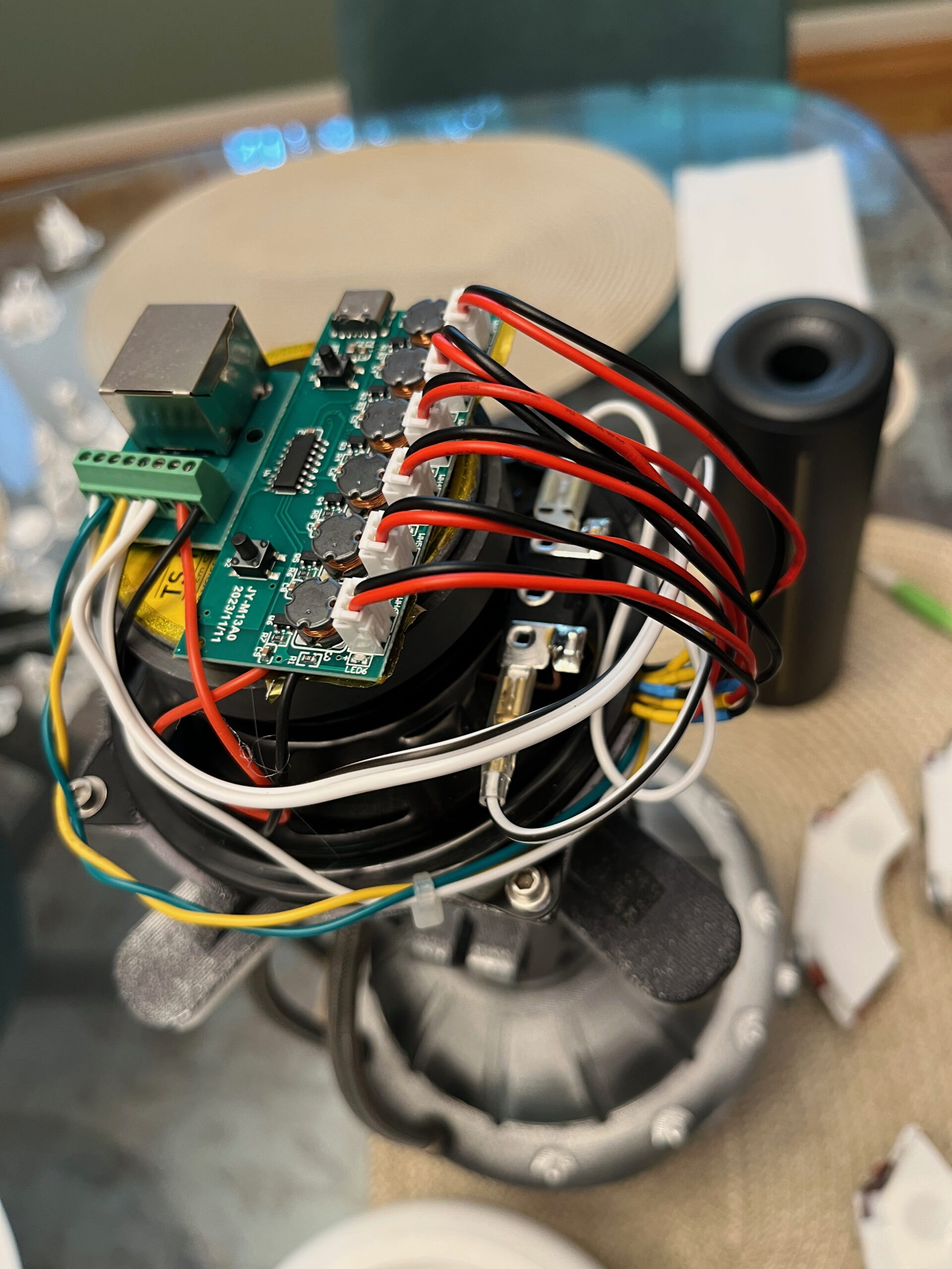
You can see the RJ45 (ethernet) breakout board next to the driver board, for easy connection/disconnection between the engine and the central electronics. There are 8 conductors in that cable, and initially I was only using 7 of them: 3 for the LED rings, 2 for the speaker’s connection to the amp, and 2 for 5VDC power to the driver board.
Here’s what the inside of the engine looks like without the modules in place:
This plan has worked pretty well, and had a couple of complications that slowed things down. First, I kept getting leaks no matter how I managed mounting the discs and their o-rings, until I found that the water was leaking through the 3D-printed surfaces themselves. Solid-looking PETG prints were apparently more porous than I realized. So I followed the Bambu Lab wiki instructions for making things watertight, and that problem went away.
The other problem was power, which I’ll explain in a separate post.