jetpack

All posts tagged jetpack

I’m not planning to make another one of these any time soon, but if I did, I made a list of what I’d do differently next time based on what I learned with this one:

  • Now that I know what electronics are involved in the central section, I’d design a mounting board specifically to hold those, instead of just haphazardly hot-glueing things on top of each other. I might even design an enclosure for that section, so it’s all self-contained with ports on the side for power and signals.
  • That holds true for the electronics on the engines as well. I could design and print a mounting bracket or enclosure for the components instead of having them glued to the back of the speaker.
  • Right now, the piezo discs on the exhaust modules use a trimmed-down version of their included silicone grommets to seal against the enclosure. This was mostly because I designed it to use o-rings, but found those too inflexible. Next time I’d see about making enough room to just use the original grommets unmodified, assuming that didn’t cause things to leak. Whenever possible, I like to make replacing parts easy.
  • The current design uses off-the-shelf relay PCBs and RJ45 breakout boards. I’d consider designing custom PCBs to incorporate those with less wasted space.
  • Now that I’m only using one output voltage from the battery pack, I’d just use a dumb 12V battery setup instead of the USB-C battery pack. In fact, I expect I’ll swap that out the next time I have the jetpack disassembled.
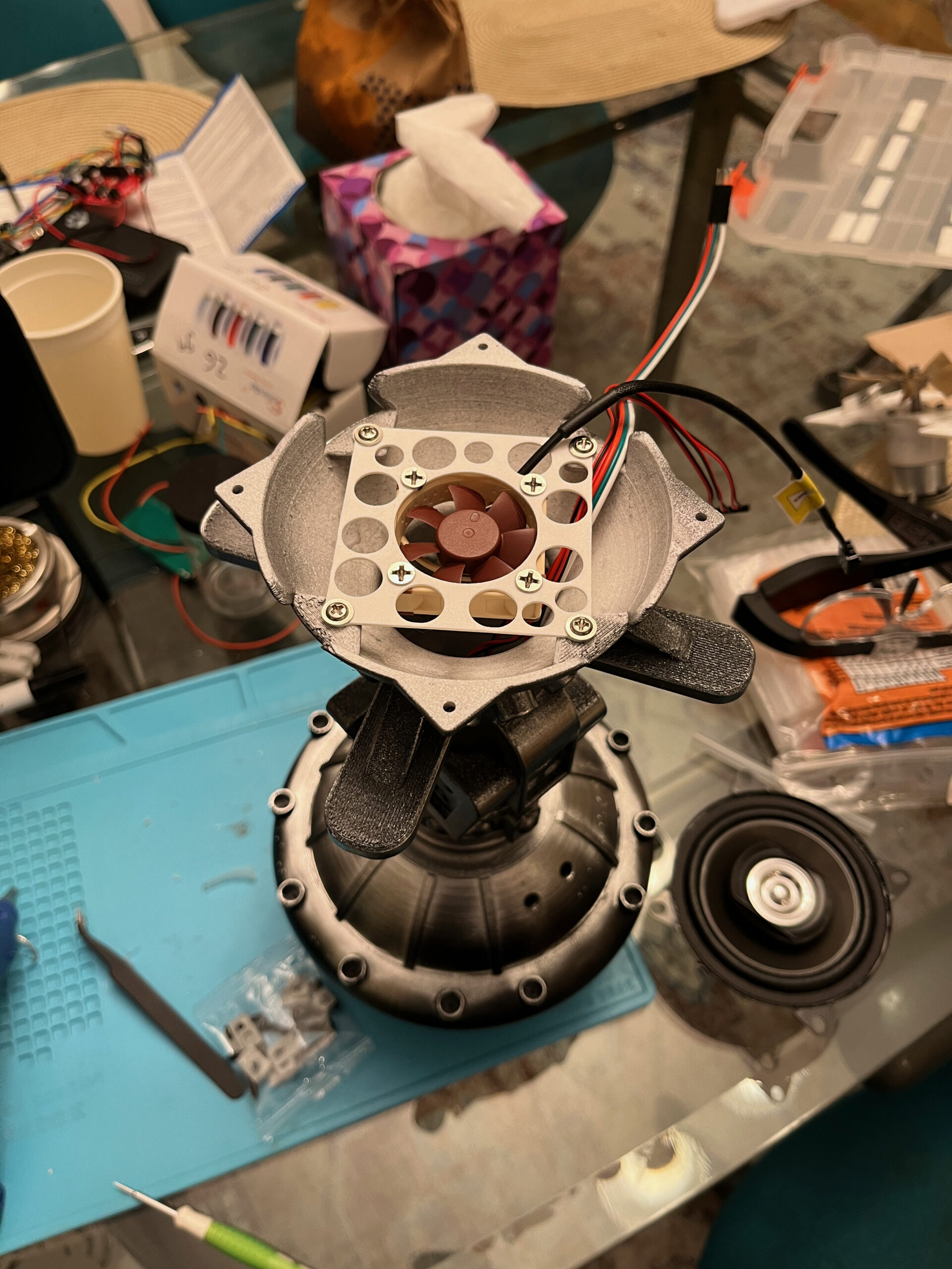
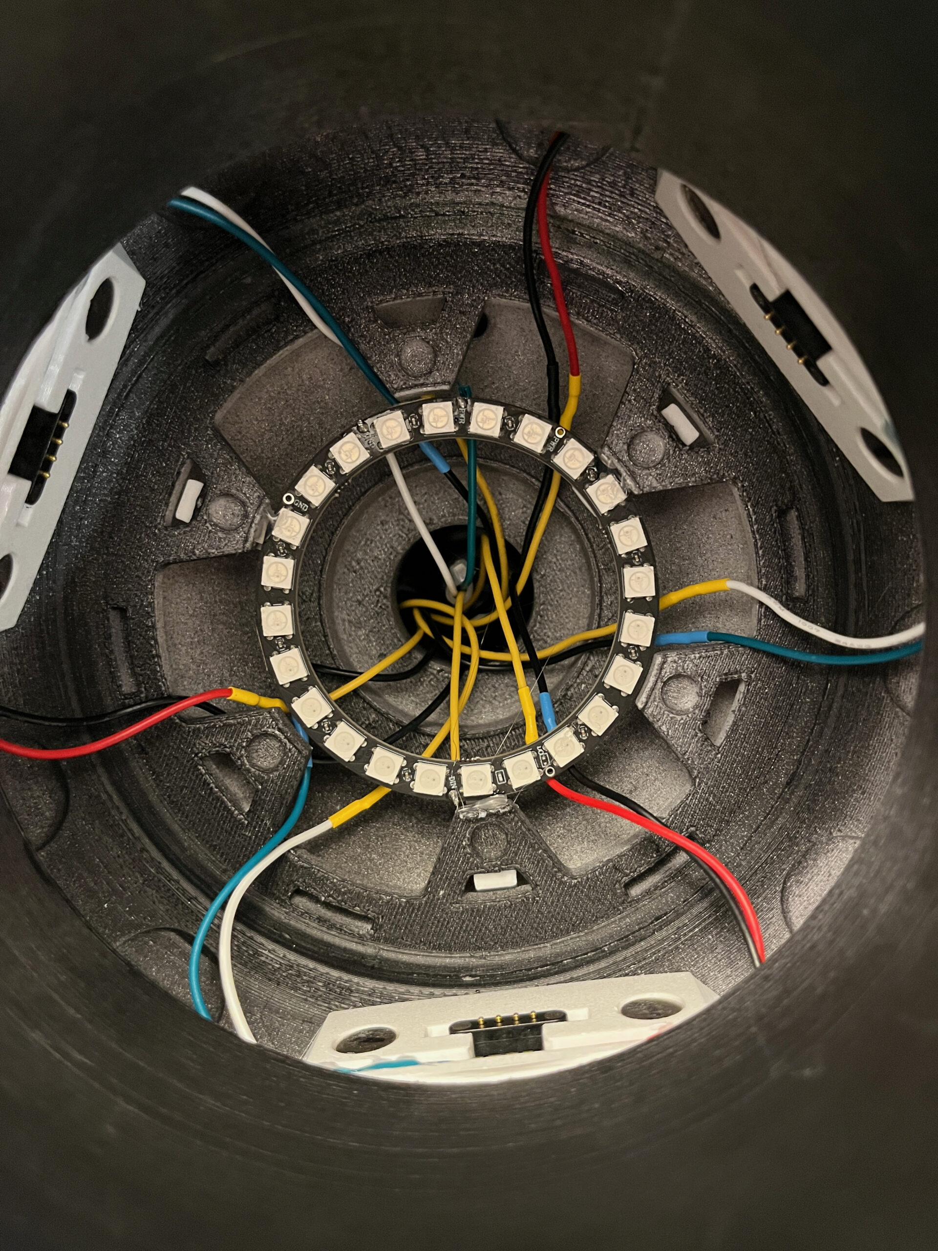
  • Better wire management inside engines: Right now there are 15 wires running from the top of the engine to the bottom (3 for the LED ring, and 2 each for the ultrasonic discs), and the wires are just kind of shoved in there. To avoid coming into contact with the speaker cone, I had the wires exit the top of the engine through the unused holes for the braided hoses on the back side of the engine, which I didn’t bother installing. I’d try to work out some tidier method of running those wires.
  • When I was painting and assembling everything, I hadn’t yet figured out the solution for a clear top-coat. Now that I have one, I’d try painting the pieces separately and then applying the floor polish, and then adding the rivets and small fins. By the time I’d figured out the floor polish part on this one, I had already attached the rivets, which prevented me from doing one final painting pass to make everything perfect.
  • To contrast with that, next time I’d try attaching the helmet fin before painting and polishing. (But after initial sanding)
  • This time, I didn’t bother with most of the post-processing sanding etc. on the engines, since most of them wouldn’t be visible, and the parts that were would be painted with matte black paint (which would show the lines less). This was tempting to skip anyway, since that part would be the hardest one to sand. But I think it would look better if it was a bit smoother, so I’d figure something out.
  • This time around, I focused on sanding and painting and polishing the outside surfaces of the jetpack, and pretty much ignored the inside. Which was fine, since it’s not visible at all. But I didn’t mask it out either, so it’s just kind of randomly semi-painted, and the paint will rub off on your hands if you are poking around the inside much. I think next time I’d mask that all off when painting, or just polish it as well.
  • I had intended to mount the small LED rings on the engines with magnets, so they’d be easy to remove or replace if necessary. The smaller magnets in question turned out to be much too weak in practice, so I ended up securing the rings with hot glue as well. Next time I might go for something a little more planned out.
  • The piston-looking actuators on the flaps lead up to go inside this little egg-shaped bump-out on the non-outward-facing part of the jetpack, and are retained in place by being attached to little plastic balls that don’t fit through the holes. The Veepy design has options for either sealing that egg-shaped compartment in, or having it open to the inside of the central body. I chose the open option, to make it easier to remove those actuator struts if necessary. But that turns out to make it easy for them to work their way upwards into the body, falling out of the other half of the actuator. I’d either come up with a better way of retaining those, or just seal them in next time.
  • The line-level audio output from the FX board goes into the audio amp with a minijack aux-in connector. I’m not crazy about that as a connector, and I’d have been tempted to solder something more direct on, but the minijack connector is surface-mount, so I might not bother.
  • I’d definitely put in more convenient access to the controls to power the jetpack off and on. In fact, I’ll probably still do that with this one the next time I have a reason to take it apart. If (when) I replace the USB battery pack with a dumb 12V battery, I should be able to have a single power switch for everything, reachable by removing a single nose cone.
  • For some reason, I never was able to get a satisfyingly clean line on the edges of the vents on the side of the tanks. I’m not sure what I’d need to do differently, but it irks me and I’d definitely figure it out on a hypothetical v3.0.
  • My solution for bending the copper pipes on the engines (cut a number of notches halfway through it so it could bend without folding) seems janky, and I’d look into whatever the proper solution is there, which presumably involves an additional tool.
  • I wasn’t as thorough with the post-processing of the parts of the jetpack that were outward-facing, i.e. the parts that are sandwiched against the leather harness. And sure, nobody will see them, But I’ll know they’re there, and if this thing is supposed to represent a work of art, I’d probably put in the effort.

What’s Next?

I’ve made references to this being attached to a leather harness, but now I need to make the thing. There’s a premade option you can buy, but I don’t think that would fit my needs without extensive modification, and at that point I might as well start from scratch. Plus I always love picking up new skills and tools. So, I found a decent-looking pattern to work off of, bought some beginner’s leather working tools, and some leather. It turns out that purchasing leather for hobby purposes comes in sizes of 12″x12″, 12″x24″, and “cow”. In my case I needed “cow”:
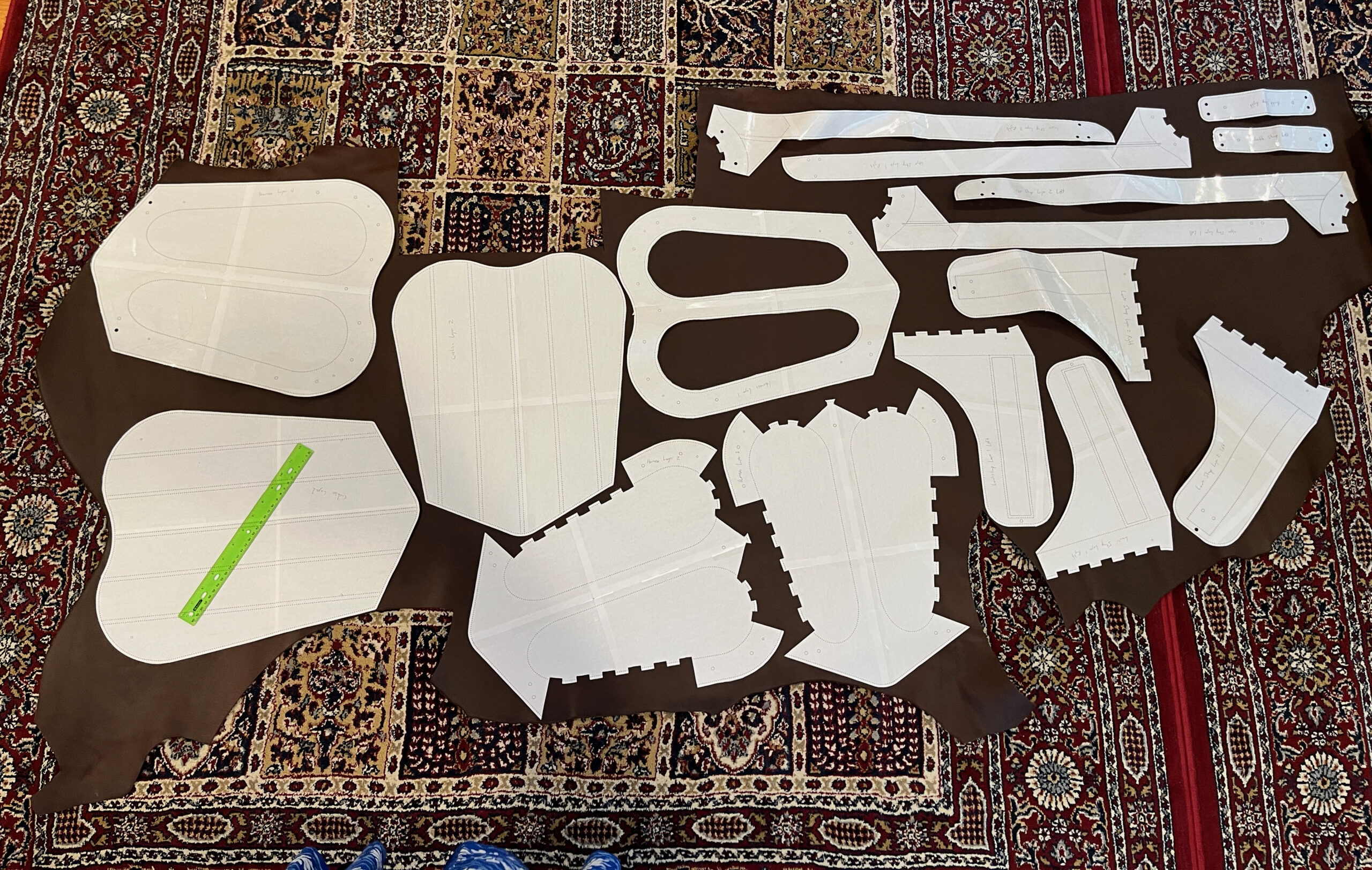
(ruler for scale)

As you can see, my rough estimates that the big piece of leather should fit everything were correct! Unfortunately, there’s not much margin for error, so I better not screw this up, or I’ll need to buy more.

So the next big step is a bunch of leather working. New tools and skills!

Beyond that, there is of course the rest of the costume. The rest of the outfit in the movie consists of leather boots, jodhpur pants, a button-up shirt, leather gloves with partial gloves layered on top (with controls for the jetpack), and an iconic leather jacket with a buttoned panel on front that usually covers the harness straps. I’m working on a feminine interpretation of this look, so I’ll be taking a lot more leeway with the rest of the outfit than I did with the jetpack and helmet. The harness will be slightly changed as needed for body shape, but otherwise it should be close to the on-screen version.
The Valor FX board is powered by a 7.4VDC battery, and its documentation didn’t mention what kind of tolerance it had for that, so I bought the recommended battery, plus a spare. That board will power the LEDs with 5V and the fan with the native battery voltage, and will provide a couple of always-on 5VDC outputs. One of those outputs is running to the wireless remote receiver board that activates the effects. There’s also a separate power switch for the Valor board, so by itself it’s pretty straightforward for power requirements and on/off control.

The audio amplifier I picked uses 9-24VDC, which is a good flexible range but doesn’t match the FX board. And the ultrasonic driver boards for the exhaust system run off of 5VDC, so that’s three voltages I need to handle.

The Valor board did have an extra 5V output that I could run to the remote trigger board and then to the exhaust drivers, but I didn’t want to further tax the little 7.4V battery. I figured 12V would be a good middle-ground for the amp, so I needed something that would provide both 12V and 5V. I came up with a clever solution, which didn’t completely work out.

My solution was to use a USB battery pack that offered multiple USB-C Power Delivery ports, which can (depending on the device’s negotiation) provide 5V, 9V, 12V, 15V, or 20V of DC power. I combined that with some handy and cheap PCBs that do the USB PD negotiation for you — just set some DIP switches to the voltage you want, plug it into USB-C, and it outputs the selected voltage from a terminal block.

This plan had the benefit that I could run both the 5V and the 12V devices off of the same battery pack, which would also be easily rechargeable or replaceable if needed. It did require that the battery pack be able to output two different PD voltages at the same time, but in my initial testing, it looked like it was fine with doing that as long as one of the voltages was 5VDC.

The little PD negotiation boards are great, and a convenient way of getting a standard voltage out of a battery pack or USB-C charger. So my plan involved having one USB-C cable running to the adapter set to 12V, connected to the amp, and another USB-C cable with an adapter set to 5V, running to the remote receiver board, which was then running to the ultrasonic driver boards.

I built out the different parts of this separately without issue, while I sorted out various versions of the exhaust solution. Once the design was settled, I reached the stage where I was could hook everything up together, and then I started running into problems.

The first problem was that the remote receiver board is only rated for 2A of output current, and the ultrasonic driver boards each draw about 1.5A when running. So they were fine when I was working on one at a time, but once I hooked up both, it triggered an auto-resetting fuse on the remote board. Thankfully, I had some little 5V relay breakout PCBs sitting around from a previous project. I could have used one of them in with the electronics in the central part of the jetpack, but that was getting pretty crowded, so I opted instead to put one relay on each engine, which required an additional signal running to the engines, but I still had one unused wire on the cat5 cables connecting them. Once I had those hooked up, the exhaust system was fine; the remote receiver board only had to power the two relays, which then switched the full 5V power to the driver boards.

The second problem was that apparently I’d missed something in my initial testing of the USB battery pack, and it doesn’t output two different voltages at the same time. If I just plugged in a 12V device, it would output 12V with no problems, but as soon as I connected a 5V device as well, the 12V output dropped out and came back at 5V. I tried a few different USB-C battery packs and they all had the same behavior, so it wasn’t just the cheap one I picked up for this purpose.

To solve this, I picked up a 12V->5V buck converter board, which does exactly what it’s supposed to. That way I can run a single USB-C cable to the battery pack, connected to the PD adapter board set for 12V, and use that to power the amplifier and the buck converter, which can then power the 5V devices. If I’d caught this limitation earlier, I might not have bothered using USB-C power in the first place, and just used a 12V battery pack. This would have made power control easier, because I could have a single DPDT switch controlling power to both the 7.4V and 12V batteries. I have some of those switches left over from a previous project, and I ordered a 12V lithium-ion battery so I could convert the jetpack over to that, but so far I haven’t felt the need to replace what’s currently working.

In addition to providing power to everything, the other considerations were charging and switching it on and off. Both batteries are attached via velcro strips, so worst-case they could be removed and charged separately. I put the 7.4V FX battery towards the top of one tank, so it can be reached by removing the nose cone. The USB battery pack is deeper in the central section, but I put a USB-C panel-mount extension cable from it to the top of one tank, so you can remove the nose cone and plug a charging cable in there.

Switching the whole thing on and off isn’t as convenient as I’d like. The FX board has a power switch, but it’s mounted to the fan motor in the central section, and the radiator has to be removed to access it. I suppose it would be easier to unplug its battery instead. The USB battery pack wasn’t perfect either — it has a button that will wake it up, and it will also wake up if a device is plugged into it. But it will go to sleep after 30 seconds if no device draws more than minimal power. The audio amp draws enough power to keep it on, thankfully. I went through some less-convenient arrangements before I got the buck converter, but now I just have the single 12V USB-PD adapter connected via a long cable running to the USB-C extension connector under the nose cone. So I can just unplug that cable to turn off the 12V and 5V devices, and plug it back in to power them back on.

But probably the next time I have a reason to disassemble the jetpack, I’ll replace the battery pack with the dumb 12V battery and a single power switch.

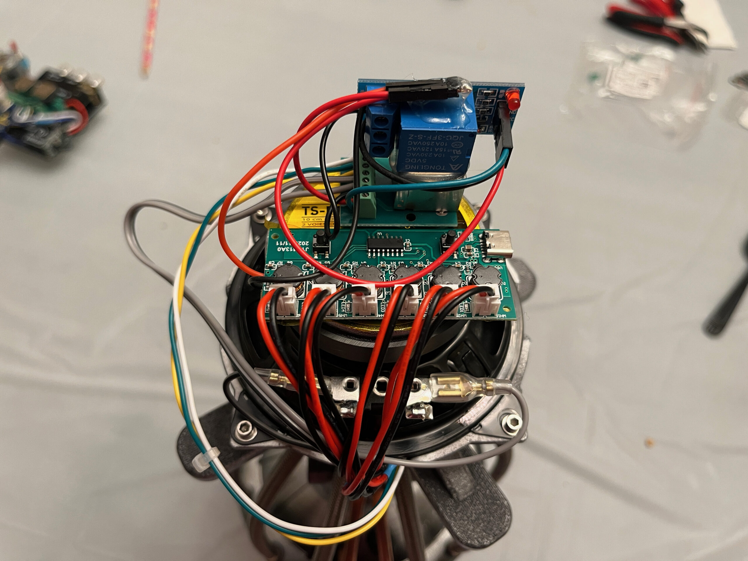
I feel the need to include some photos with this, so here’s a shot of the hardware on top of each engine:

Top to bottom, you can see the relay breakout PCB, then the RJ45 breakout board, then the 6-disc ultrasonic driver board, all mounted on the back of the 4″ speaker.

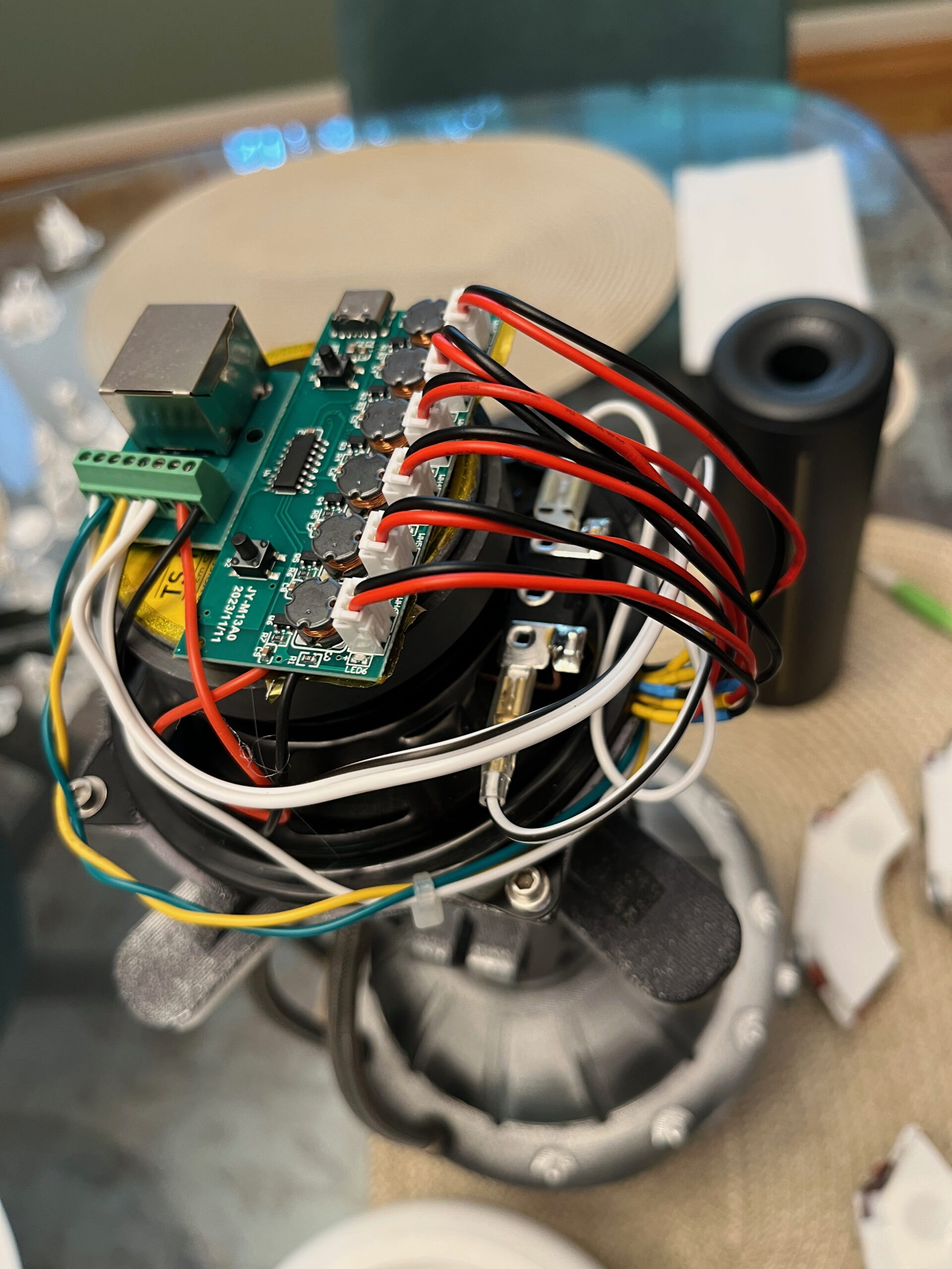
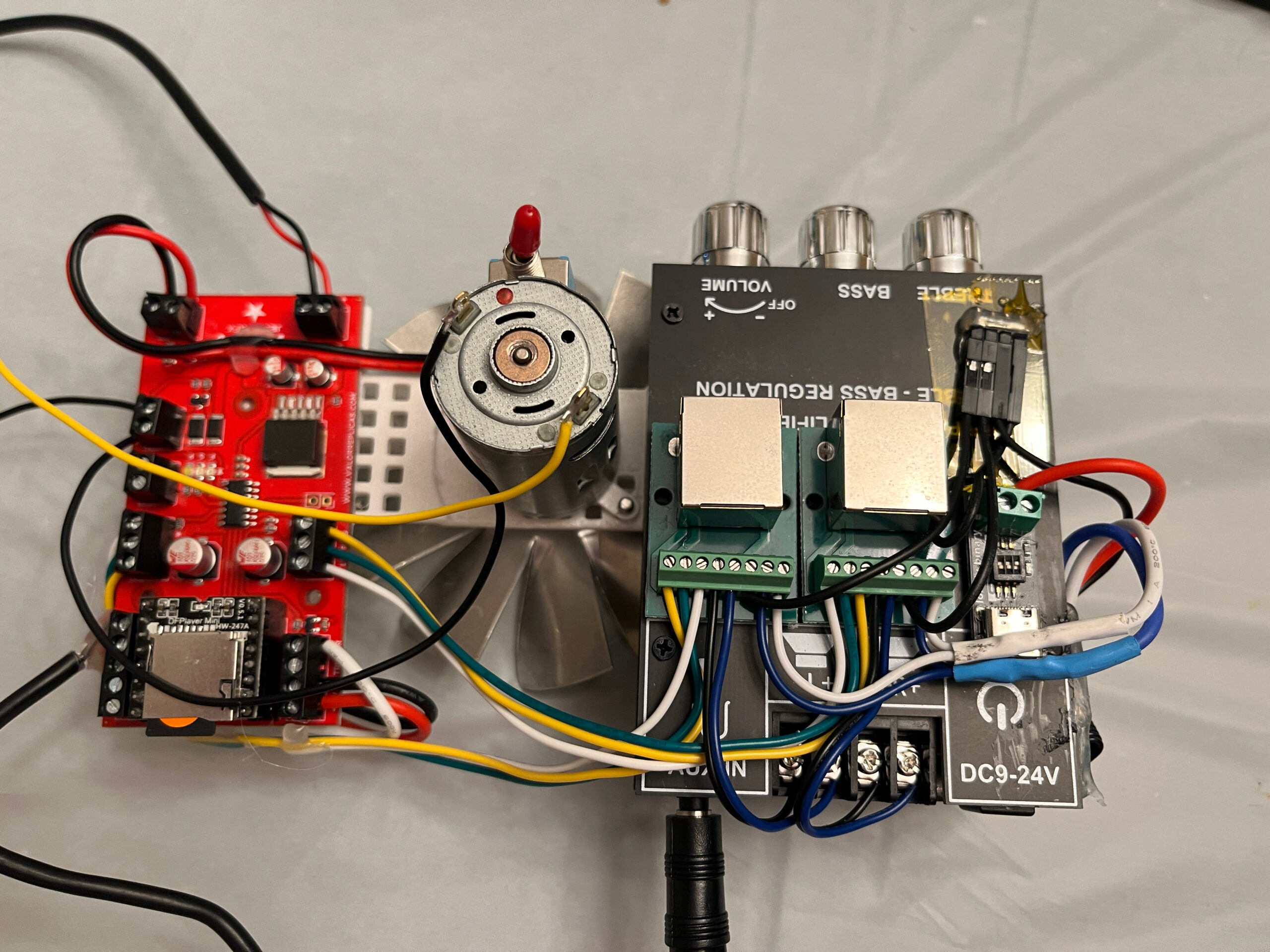
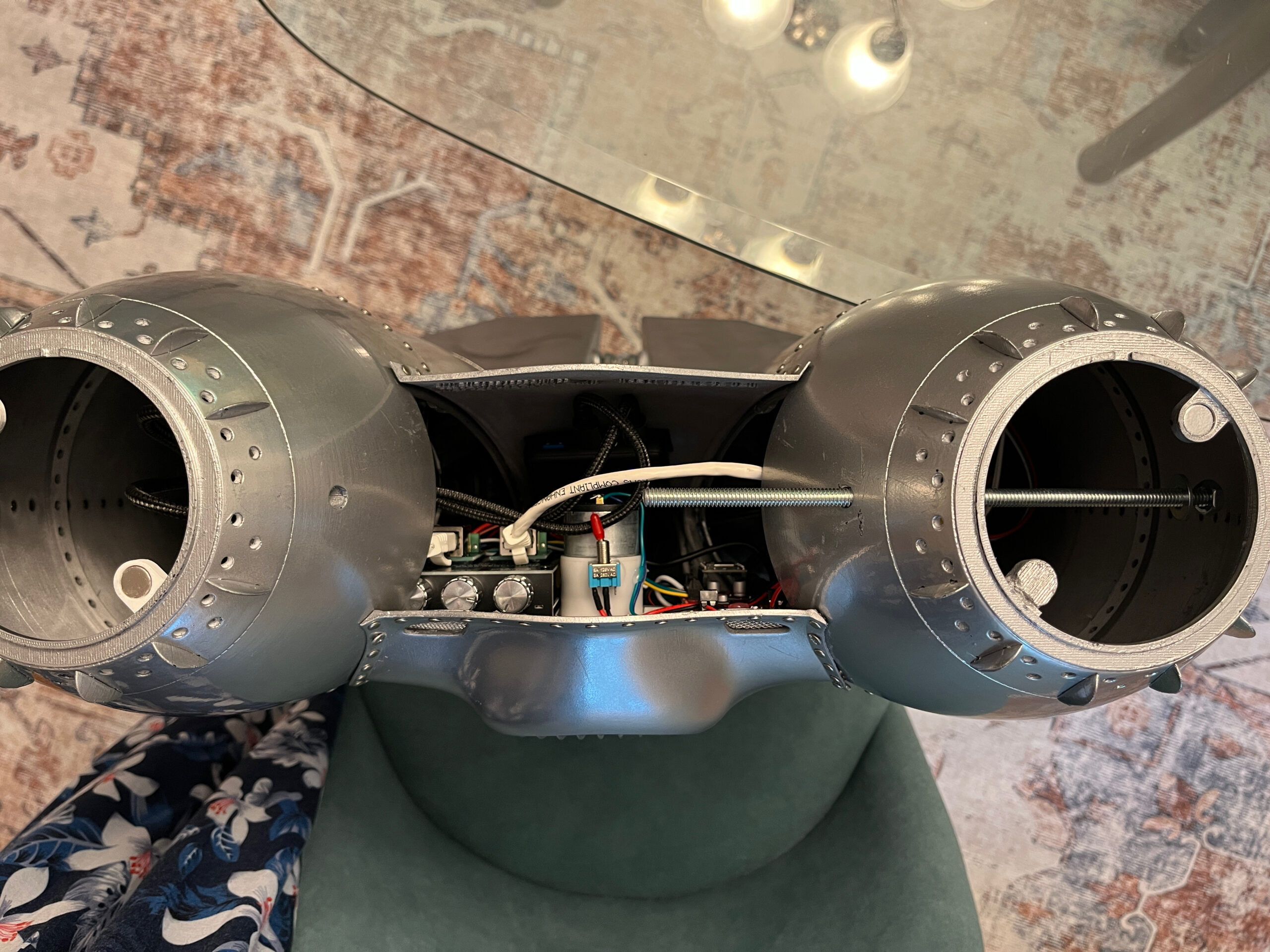
And here’s a view of the central section from above, when the radiator is removed:

This is without the engines installed, or else you’d see the tops of them in the tanks. In the central section, you can see the audio amp with the RJ45 breakouts on top of it, then the fan motor with power switch, and then the FX board. There’s also a good view of the threaded rod that secures the radiator and holds the top of the tanks in position.

Once I saw the animated lights from the Valor FX LED rings, I really wanted to see them lighting up some kind of exhaust. You can buy small battery-operated fog machines for this purpose, but I didn’t want to have to worry about potential sensitivities people might have to the special liquid used in those. I was particularly intrigued by the existence of cheap, readily-available coin-sized piezoelectric discs that used ultrasonic vibration to turn water into vapor. These get built into little humidifiers a lot, and you can get one with a driver board that runs off of 5VDC for a few bucks. I picked one up and tested it out, and it looked great. The only problems were a) it wasn’t nearly enough vapor, and b) it was designed to emit it upwards. Also I’d have to fit whatever I wanted into the space inside the LED rings, without blocking too much of the hollow channel in the middle of the engine where the sound comes out, and make it feasible to refill the water reservoir and replace the piezo discs (which are reportedly a consumable item).

As a first pass, I picked up some small watertight storage bottles that would (barely) fit in the required area, and designed & printed an enclosure to hold three of the discs in the lid. This way, the bottle could be unscrewed for filling or emptying. It would still emit the vapor upwards, but I figured I’d stick a small fan up at the top of the engine, blowing that downwards.

The fan options did not work. I started out with quiet little fans that could fit entirely underneath the speakers, and they didn’t move nearly enough air. I tried replacing them with larger fans that would require making a mounting bracket for the speaker, and just never got a decent result.

So, new plan: how effectively could I just mount the emitters upside down? They came with little silicone grommets, but their included plastic enclosures were definitely not designed for any non-upright arrangement. I tried designing a new enclosure for them that used some nitrile o-rings, and it seemed promising. Also the 3 emitters didn’t seem quite sufficient, so I came up with this:

This assembly held five emitters, with a tube that would lead up and out of the top of the engine, all the way to the top of the tank so it could be refilled via the nose cone openings. Some aspects of it looked good, but it just wasn’t the right answer. So I took a step back and questioned some initial assumptions.

The answer I settled on was to replace the LED rings with smaller versions of the same thing, then I could fit the exhaust emitters around the LEDs rather than in the middle of them. I found a compatible LED ring with the same number of LEDs, that was a drop-in replacement, and about as small as it could be and still fit those components. (I eventually realized I could have tried flex-cable mounted LEDs and wrapped them around the inside circumference of the engine nozzle, but this worked well.)

With the smaller LED rings, I could fit six emitters, which seemed like a good number — one of the available kits included a cheap 5VDC driver board that handled six discs at once, and I figured I could mount one of those on each engine. I still wanted them to be serviceable and easily fillable though, and designing a donut-shaped exhaust assembly seemed like it was asking for trouble.

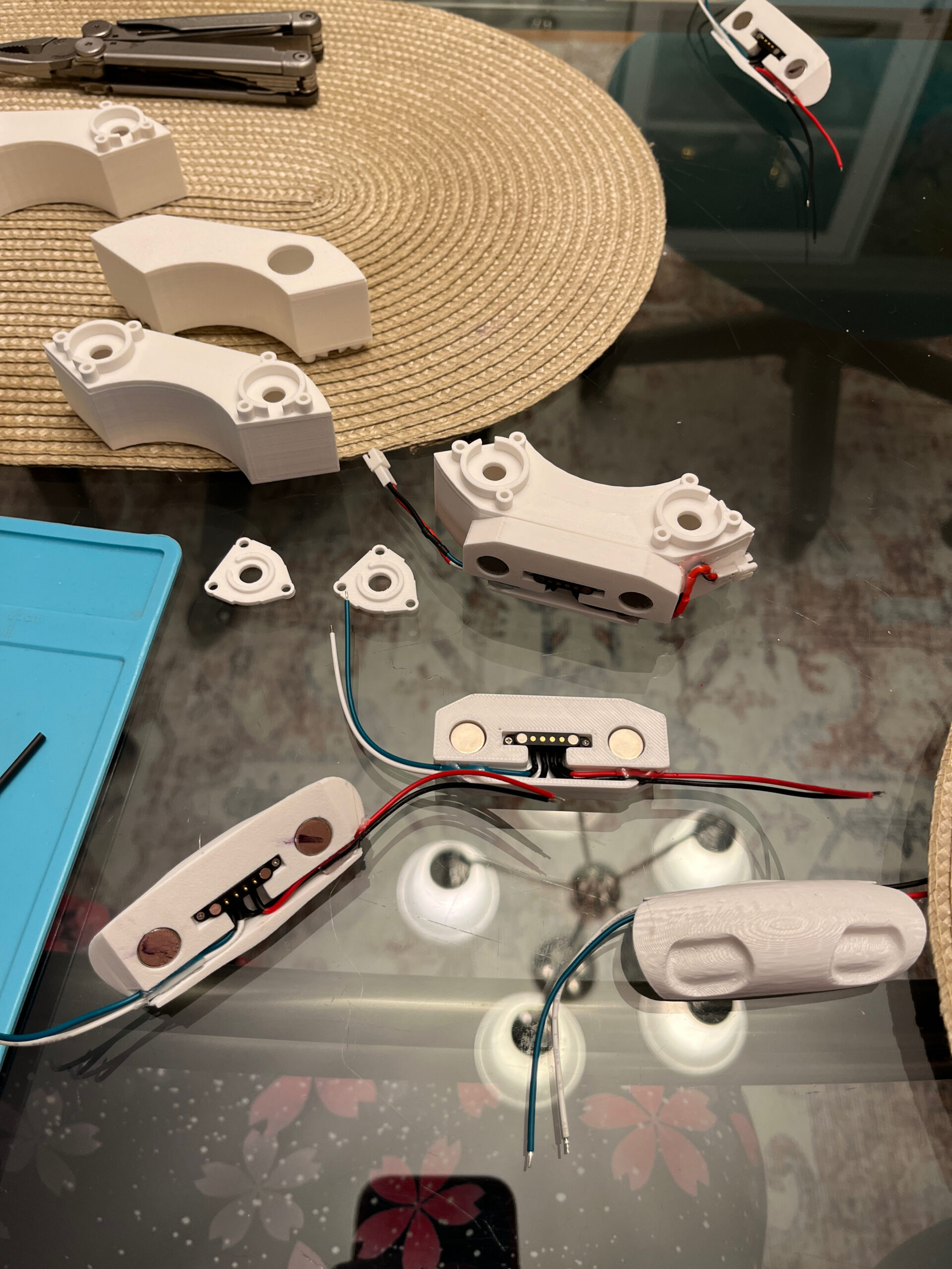
So here’s my solution: I designed separate interchangeable exhaust modules, each of which contains 2 emitters and its own little reservoir. (And a printed TPU plug you can pop out to refill or empty them.) They attach magnetically, and even have little magnetic pogo-pin connections for the electrical hookups. You can see the modules up top, and the rounded mounting points at the bottom. Here’s what it looks like with them in place on an unpainted test engine:

There is just barely enough room in the middle for the smaller LED ring. The idea is that this way, I can reach up into the engine and just pull the modules out in order to refill or service them. And installing them consists of reaching up into the engine and clicking them into place.

The driver boards are hot-glued onto the back of the speakers at the top of the engines, and the wires from the module mounting points run up through the center channel of the engine:

You can see the RJ45 (ethernet) breakout board next to the driver board, for easy connection/disconnection between the engine and the central electronics. There are 8 conductors in that cable, and initially I was only using 7 of them: 3 for the LED rings, 2 for the speaker’s connection to the amp, and 2 for 5VDC power to the driver board.

Here’s what the inside of the engine looks like without the modules in place:

This plan has worked pretty well, and had a couple of complications that slowed things down. First, I kept getting leaks no matter how I managed mounting the discs and their o-rings, until I found that the water was leaking through the 3D-printed surfaces themselves. Solid-looking PETG prints were apparently more porous than I realized. So I followed the Bambu Lab wiki instructions for making things watertight, and that problem went away.

The other problem was power, which I’ll explain in a separate post.

Once it became clear that the jetpack might be comparable in appearance to the production hero props, I was motivated to put in a lot of extra effort. Among other things, I decided that adding electronics effects was something I wanted to do now, as opposed to maybe something at some point in the future. As mentioned, the Veepy jetpack design included mounting options for engine speakers (both 3 and 4″ speakers, seriously that design is so good), LED rings in the lower engines, and a central fan motor and PCBs for electronics.

A lot of the motivation for the project is learning new skills (and collecting their associated tools), which I always love. With my previous microcontroller work on vintage keyboard conversions, I could certainly have come up with an effects solution from scratch. But my time does have value, and I’m happy to spend money on solutions that are probably better than whatever I’d have come up with.

So, I ordered the Valor Jetpack FX Kit, and I’m certainly pleased with it. It’s a single PCB (with a daughterboard handling audio) that fits on the Veepy mounting bracket, it comes with RGB LED rings that mount onto the Veepy LED ring mounting points, It comes with a single cheap 3″ speaker, and connections to a fan motor. It’s powered off of cheap, readily available lithium-ion batteries marketed for heated gloves, and it has external connections for the activation trigger, an on/off switch, and a couple of always-on 5VDC outputs.

The Valor FX board includes additional instructions/diagrams for some upgrades: powering and hooking up a wireless remote trigger, and hooking up an external audio amplifier, since the built-in amp is pretty weak. I went with both of those options.

(This isn’t the final version of the central electronics, but it’s close. The Valor FX board is on the left, the fan motor is in the middle, and the audio amp is on the right. The amp has a couple of RJ45 (ethernet) breakout boards on it for the connections to the engines.)

For the audio amplifier, I picked up a cheap little class-D amplifier with flexible power requirements (9-24v) and bass/treble adjustments. It has bluetooth support which I didn’t want or need, but it looks like all the options in this category include that now. I planned to power the amp off of 12VDC. To go with the amp, I picked up a pair of Pioneer 4″ speakers and mounted one on each engine.

I bought the RF remote trigger boards that were recommended in the Valor instructions. They consist of a small PCB with four wires sticking out — input (VCC/ground, the VCC will take a good range of voltages) and output (not a relay like I expected, but the same VCC/ground as the input. Surprisingly the output VCC line is connected all of the time, and it switches the ground connection to open or not. Odd. The output current is limited to 2A or so, and they mean it — this became important later when I was making the exhaust system. The included RF remotes have 2 buttons, but I was only planning on using one. The remote receiver boards had two nice features that were very convenient for me: first, they had no problem pairing the same remote to two separate boards, which means I could use separate receiver boards to trigger the exhaust and FX board, but triggered from a single remote. Secondly, they were configurable for different behaviors, so I could set it up as a momentary button instead of an on/off toggle. This was critical if I was using two of the receivers with one remote, because I wouldn’t want the receivers to get out of sync with their power states.

The LED rings consisted of 24 WS2812B units on ring-shaped PCBs, individually addressable. The rings were each connected to the FX board with 3 wires, and it made some nice red/orange/yellow animations to simulate the light from the engines. I felt like the light would look a lot better if it were illuminating some kind of fog or mist, which turned out to significantly expand the scope of the project.

The Valor FX board is also designed to drive a fan motor, and seems to use the full battery voltage (~7.4VDC) for this. The Veepy jetpack instructions called for a specific size of motor (both for mounting holes and for the fan shaft), but the only readily-available motor I found that was an exact match was designed to run at 200RPM, accomplished by having an integrated gear box. This worked, but ran a bit slower than ideal, and I didn’t like the plastic gearbox sound that it made. So I kept my eyes out for an alternative, and eventually I settled for a motor that didn’t match either size requirement. It was too small for the mounting points on the jetpack’s mounting bracket, but I designed and printed a mounting adapter. It also had a smaller shaft, so I printed something for that as well. That fan was great, and it was fast. It didn’t have the gearbox sound, but it did sound like a fan moving a lot of air. I ordered a cheap PWM motor speed controller board and wired that up, and it was perfect for letting me dial in the speed I wanted.

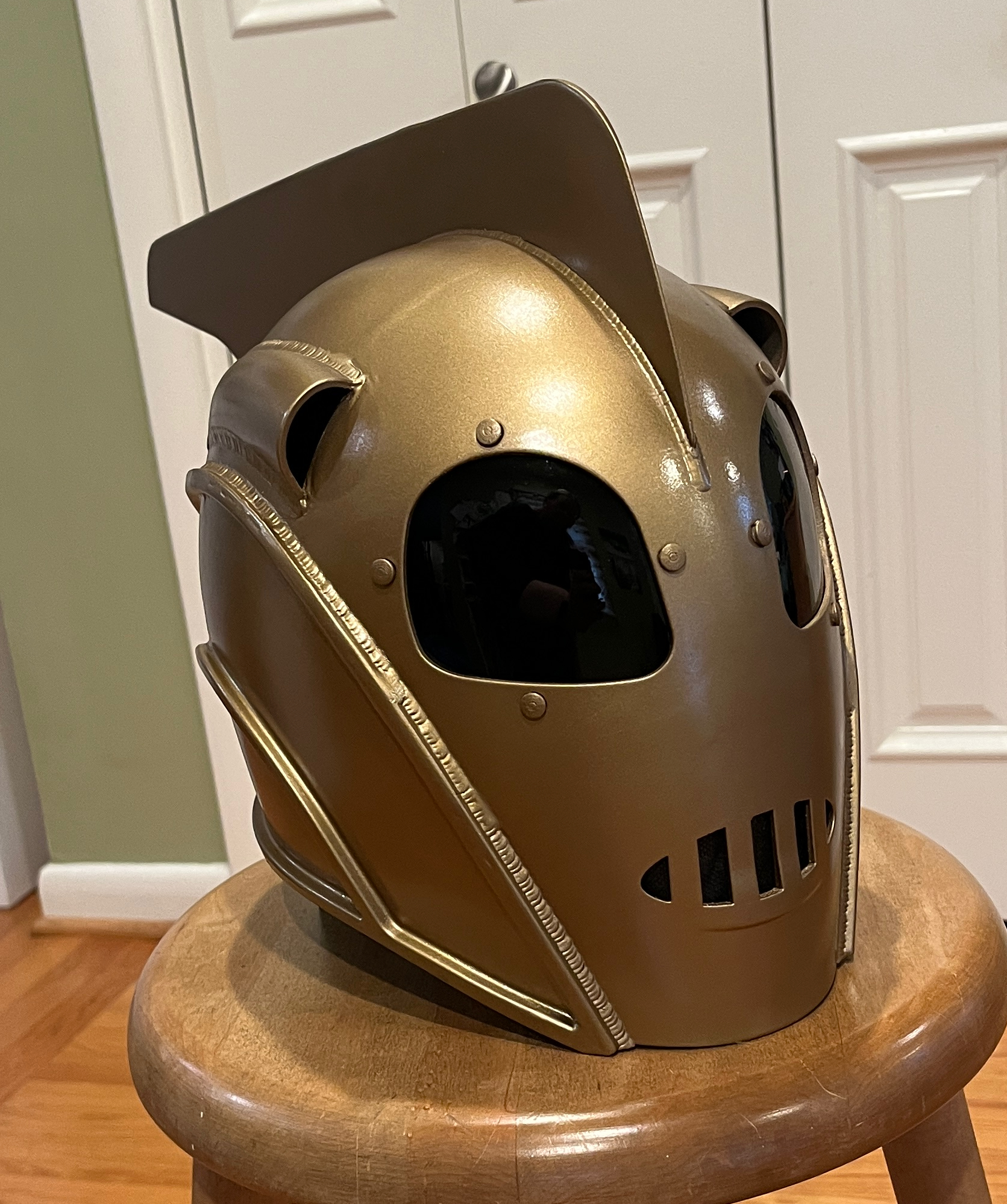
First off, here’s the end result:

The 3D model I used for this was this design from Etsy. It was well-designed, and looked like a closer match to the on-screen prop compared to the other models I saw.

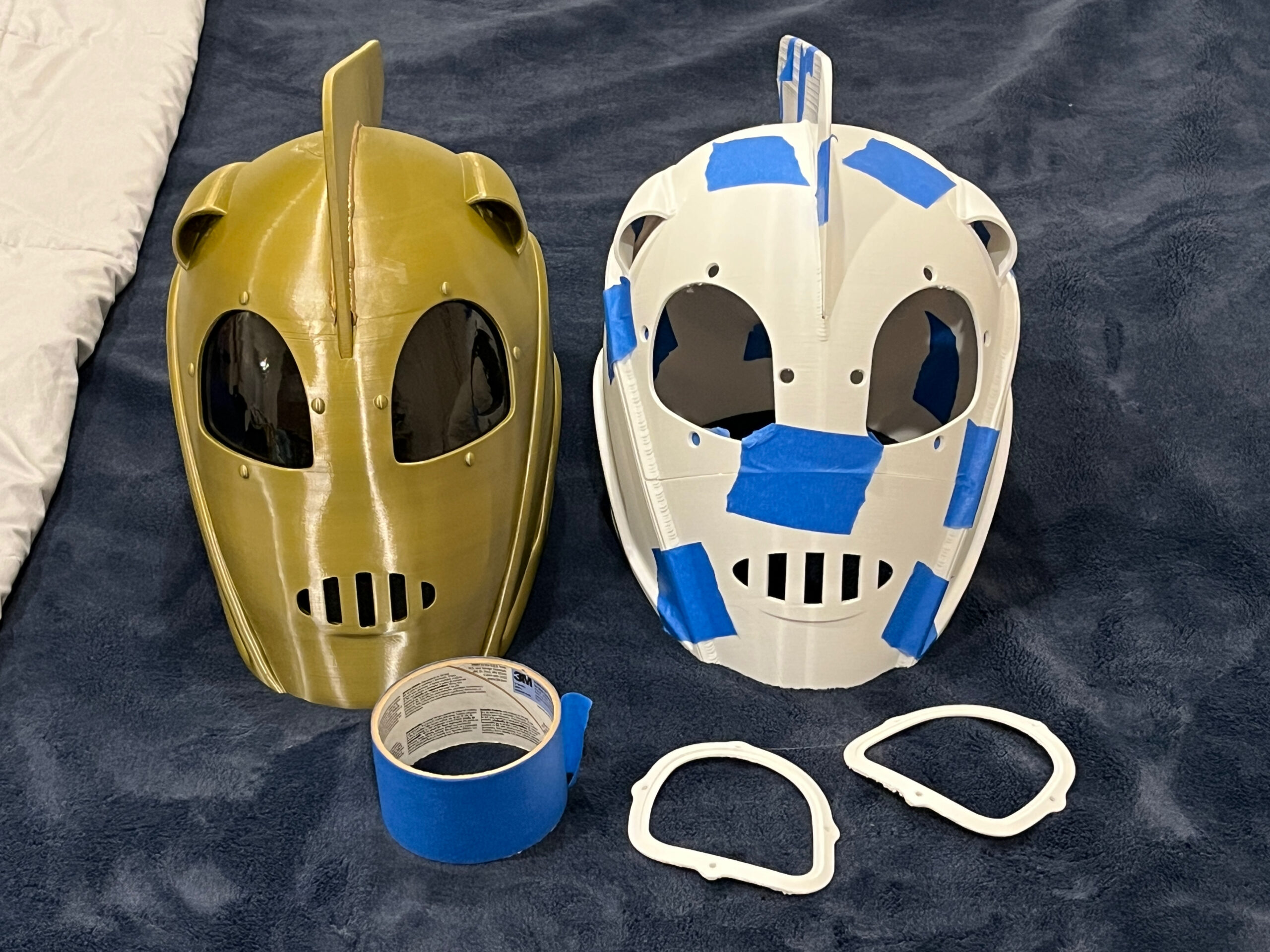
Like the jetpack, I printed it in plain white PETG on my Bambu Lab P1S, then followed the same steps for sanding and painting from my previous post. (side note: the weld lines are part of the 3D model itself.) Unlike the Veepy jetpack model, this one came segmented in ways that would result in visible seams. Or at least it would with my printer — it did include a model of the whole helmet at once, if that’ll fit on your print bed.

Here’s a comparison picture between the old and new helmets, which also shows the (taped-together) sections of the new one:

To deal with the seams, I originally figured I’d use some classic Bondo auto-body-repair stuff, but at one point when I was picking up supplies, I happened upon the much more appealing plastic resin goo that cures immediately under ultraviolet light. I was an instant fan of that stuff — take your time applying it, it won’t harden until you want it to, at which point you can cure it immediately and not wait to continue working on it. It’s nice and sandable after curing, too. I used that stuff to cover up the seam lines, as well as to smooth out the top surface lines on the jetpack flaps, and even to extend part of of the central section of the jetpack that didn’t quite print perfectly. Note that this stuff heats up a surprising amount when it’s curing, so you don’t want to be holding it when that happens.

This may have been a mistake, but I painted the top fin separately from the rest of the helmet, and then tried to glue it in place. Even after sanding the relevant spots, it was an incredibly tight fit. If I redid things, I’d try attaching it before painting.

The lenses were another tricky element. Those are tinted acrylic, thermoformed to the appropriate shape. The shape you’re using to press the hot acrylic sheet against is called the Buck. You wouldn’t want to 3D print the buck itself, because it would deform the printed plastic. The 3D model for the helmet included a model for an inverse mold of the buck, into which you can pour Plaster of Paris to make a solid buck that can survive oven temperatures.

Once the paster bucks were made for each eyepiece, I cut some pieces of 1/8″ thick tinted acrylic sheets to slightly larger than the shape I needed. I heated up an old toaster oven to 450-500F, and put in the buck with the acrylic piece on top of it, and waited a few minutes for the acrylic to visibly sag, indicating it was suitably bendy. It won’t droop enough to just flow over the buck like melted cheese — you need to force it into the shape. The best solution I found for that was to take a smooth silicone project mat and lay it over the piece, then press down hard on it with both hands. The silicone mat got warm, but not hot enough to burn me. Once the lenses were the right overall shape, I trimmed them down to the exact right shape with a dremel tool.

I wanted something to black out the mouth holes without restricting airflow, because otherwise I knew from my previous helmet that it would fog up the inside of the lenses pretty quickly. I had tried a few different solutions on the previous helmet, but eventually landed on the thing I used for this one as well: I took a black N95 mask from my COVID-days stash and cut out the outer black layer of it. It lets air through just fine, and doesn’t cause the lenses to fog up as much.

The inside of the helmet has a bunch of generic helmet padding stuck on it so it doesn’t rattle around on my head, and I made a quick fake leather chinstrap for it. I’ll be replacing the strap now that I’m starting on the leather work for the jetpack harness.

Oh, one last thing. For the first helmet, I was concerned about it being awkwardly sized, so I improvised a method of determining the proper amount to scale it in each direction such that it fit my head, but just barely. I took long LEGO plates and built a bit open rectangle and adjusted it in or out until I could just fit it over my head without issue. Then I measured that. Then I printed the single-piece version of the original helmet at about 30% scale, and measured the head opening with calipers, and scaled that up to 100%, and did the math to determine to appropriate scaling in each dimension. For the new helmet, I did the same thing, using the same LEGO frame as before. And once I printed the 30% version an scaled up its measurements, I found that its head opening was within a couple of centimeters of the target size. So no scaling needed. Fortuitous!

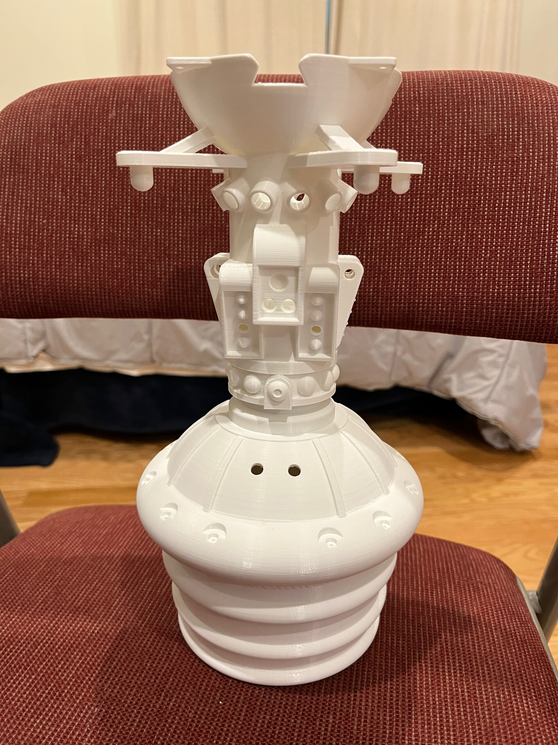
All of the pieces were printed using plain white PETG filament, so everything came out looking this this:

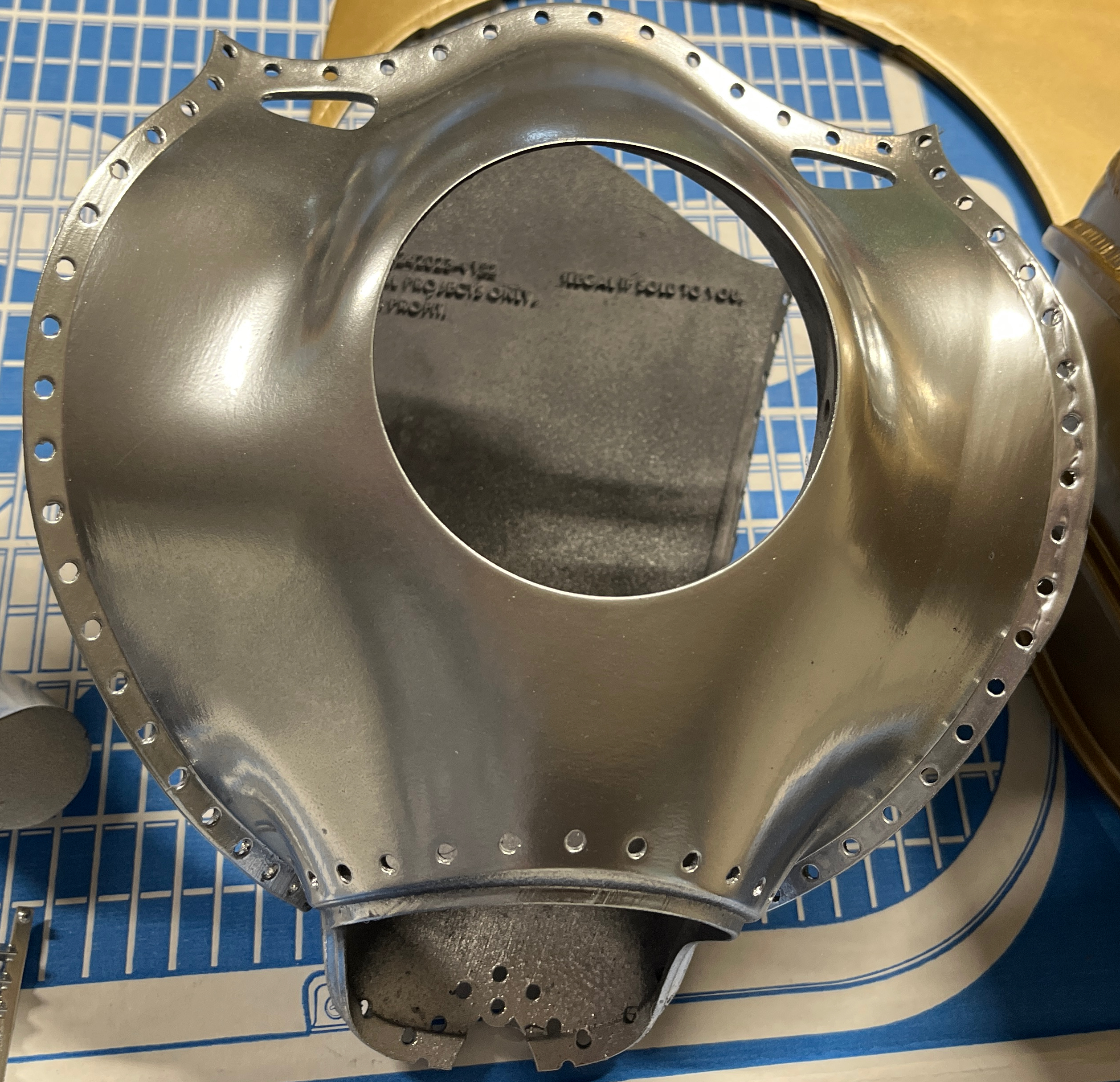
Painting anything like this was a new experience for me, so I learned a number of lessons along the way. I don’t have an airbrush, so I was going to be using regular spray paint cans, which can give a good metallic-looking finish if the surface is sufficiently prepared for them. Spraying chrome paint on the parts straight out of the printer would look awful, because the surface needs to be smooth. The shiny reflective paint will highlight every non-smooth detail on the surface, and every one of those will make it look less like metal. That means the visible layer lines from the 3D printing process have to be smoothed out, and so does any other disruption in the surface.

I went through some trial and error through the project, but in general I worked over the parts with a low-grit sandpaper (always wet sanding, to avoid making a cloud of plastic particulates), then put on a layer of sandable filler primer to help fill in the gaps, then (wet) sanded that with a medium-grit sandpaper, then repeated those two steps if it seemed necessary. Once I got things looking about as smooth as the primer would get, then I’d put down a layer of glossy black paint, and then go over that with a high-grit sandpaper. Then I’d bring out the chrome spray paint, doing lots of quick passes from slightly further away than the rest of the paint. Before any spray-painting pass, I’d wipe the surface down with a microfiber cloth, then with a tack cloth to make sure the paint wouldn’t hit some errant bit of dust or lint.

Once I got this process down, the pieces started looking incredibly metallic:

This was the first piece that I successfully got a good metallic finish on, and at this point I was stoked. I always intended to make something better than the first jetpack attempt, something that would make the first one look like a toy. But at this point it became clear that I could potentially make something indistinguishable from the on-screen props, and that inspired me to put in a lot of extra effort. I think this was also the point when I decided to add electronic effects to it.

The downside of that metallic finish was that it was _fragile_. Handling it rubbed paint off on my hands, and it dinged visibly and easily. I needed to protect things, so I grabbed a can of clear-coat spray protectant from the same brand of spray paint.

This was a mistake. Do not do this.

This was one of the first big lessons I learned here: I guess the clear-coat spray paint can be used successfully over regular colors, but using it on top of metallic paints just ruined the finish. I eventually found an explanation: the metallic spray paints are basically clear paints with tiny metallic-looking particles suspended in them, and when you spray it on something, the metallic particles stick to and coat the surface that you’re painting from inside that suspension, which is why it needs to be that smooth. But if you then spray the clear coat on it, it uses the same solvent as the metallic paint, so it just loosens up all of the metallic particles and lets them float around loose in the suspension, losing the smooth shiny surface. I saw some reports that you could successfully do this, but the steps were very fiddly and seemed to rely on a lot of luck.

Trying to find what people used as an alternative was tricky, because a) lots of people who are serious about this sort of thing are using airbrushes, which have different constraints, and b) the main product that people recommended no longer exists. The product in question was Future Polish, some brand of clear floor polish. It’s gone now, but I picked up a random brand of clear floor polish, squirted some onto a paper towel, and wiped the pieces down with it, and that seems to be working out well so far. It doesn’t look quite as good as it did with just the paint, but it’s a lot more durable.

So the main body of the jetpack was all done using chrome Rust-oleum spray paint. I tried their silver option, but that had a glittery finish that didn’t look right. The nose cones are a slightly different color in the movie, and based on a tip I saw online, I used Tamiya TAM85075 spray paint for those, and it seems like a perfect match. For the helmet and fan blades, I used Rust-oleum’s “metallic champagne bronze” and it seems fine.

If this was the kind of project I did with any regularity, I’m sure I’d pick up an airbrush and it would help. But I’m happy with the output of this process.

To start off, here’s what we’re talking about. You’ll want sound enabled for it.

This second attempt at a replica jetpack was also 3D printed (on a Bambu Lab P1S) using PETG filament, sanded and painted to achieve a metallic-looking finish. The 3D model was the “Veepy Jetpack” design, which is sadly no longer available. I am stunned at how well-designed this model is, not just in terms of being screen-accurate, but also how well things are engineered to support successful printing and assembly. There are even aspects that facilitate maintenance of it, something that I tried to continue in other areas of the build. The model was also designed to accommodate effects hardware, in order to provide lights and sound and a moving fan.

The Veepy design also incorporates off-the-shelf hardware components when possible, for things like the flap actuator parts, the braided hoses and copper pipes on the engines, the fan, and hundreds of tiny rivets. Having the rivets be a separate component not only made them look more realistic, but it made the sanding process easier without having to work around hundreds of little bumps.

To make maintenance easier, the nose cone sections are held in place with magnets, and can be carefully pried off. That gives access to the inside of the tanks (if your hands are small enough). The engines rest in a bracket inside the tanks, and are secured with a single screw each to keep them from popping out of place. Removing that screw makes it possible to remove the entire engine, at which point the tank is empty. The tanks are attached to the central section at the bottom by some 1/4″ screws, and at the top there’s a long threaded rod running from one tank to the other, through the radiator section. Those parts are designed so that once the nose cones are removed, you can unscrew the nut from one end of the threaded rod, slide it over to the other tank, and pull out the radiator. At that point you have access to the central section from the top, which is useful since that’s designed to contain the effects electronics.

I took things a step further and worked to keep the tanks separable from the central section if necessary. The little rivets are all super-glued into place, but the ones that would connect the central piece to the tanks are only glued to the central section. That made the tanks separable, but it would leave a small gap visible between the tanks and central section when things flexed at all. To counter that, I removed a handful of strategically-located rivets and replaced them with threaded fake rivets that can be secured from both sides. These are normally called Chicago Rivets, and I found some that worked for it, but installing and removing them was really fiddly. So instead I took some long-ish M3 stainless steel screws, filed the heads down until they looked like the rest of the rivets, and secured them with wingnuts on the back side. Now the tanks are securely attached to the central section, but I can undo that part and remove them if needed.

I think the only other tweak I made to the Veepy design was to replace a couple of threaded wood inserts with head-set inserts, because I was afraid the wood inserts would end up breaking the 3D printed plastic. Regardless, the Veepy design was incredibly impressive, and it inspired me to put in the extra effort necessary for other aspects of the project.

It’s worth noting how much detail the Veepy model puts into parts that generally won’t be seen: Here are the engines, which are mostly covered up when installed in the tanks:

The braided steel hoses are real, along with the brass compression rings on them, and the copper pipes. I didn’t have a proper tool for bending the copper pipes, so I used a dremel tool to cut a bunch of slots partway through the pipe in the areas when it needed to bend, which made it possible to bend it without just folding the hold thing flat.

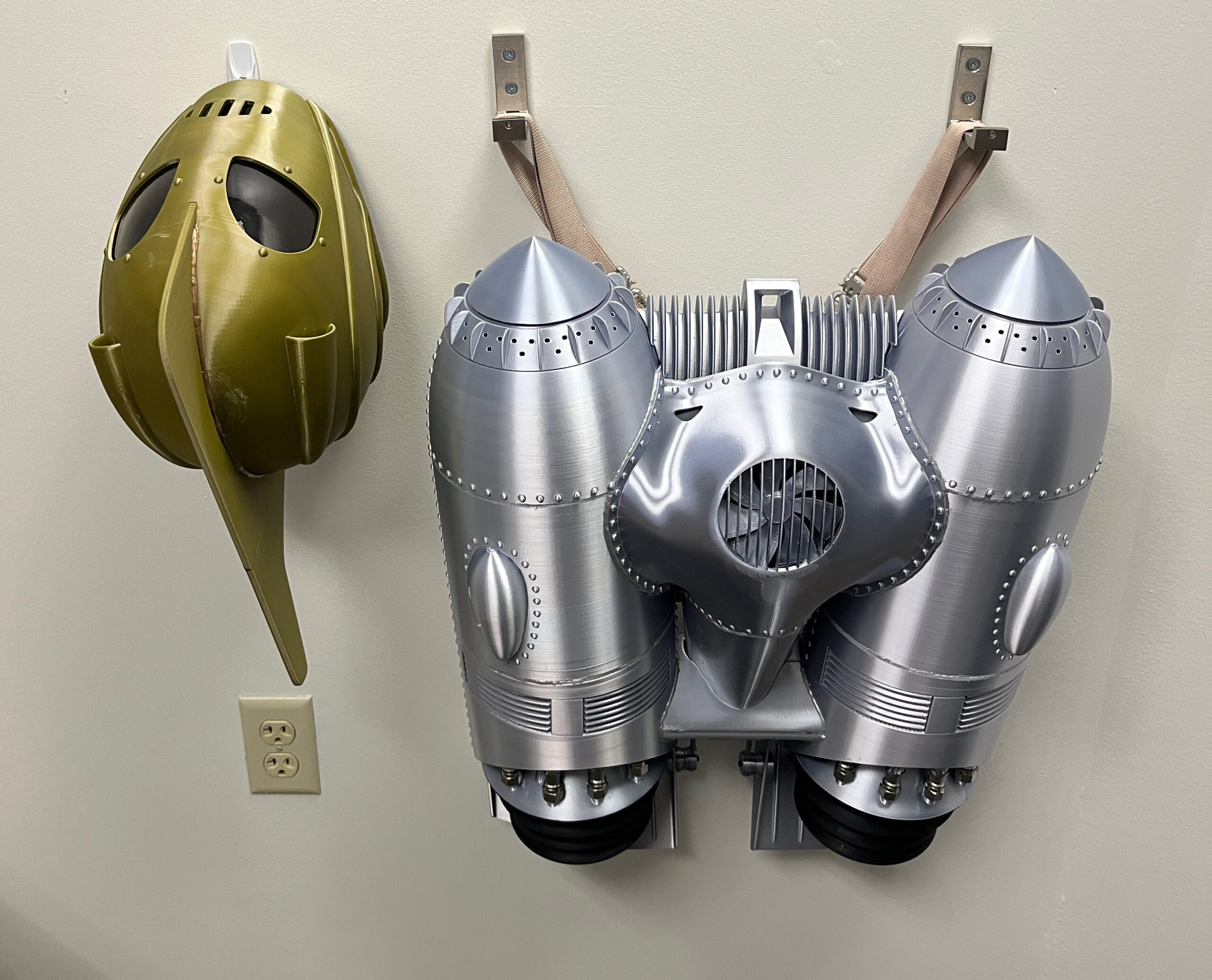
I have long been a fan of the 1991 film The Rocketeer, and especially the iconic design of the hero’s jetpack and helmet. A few years ago, I thought “why do I even have a 3D printer if I’m not going to make a replica jetpack?” So, I found some decent free STL files and printed them out using metallic-looking “silk” PLA filament. The proper approach to something like this would involve a ton of sanding and painting to get a realistic metallic look, but I wasn’t going to commit to that kind of effort. The end result was pretty satisfying and well-received:

That’s them hanging on my office wall. I filled in various seams on them with metallic-looking hot glue that did a reasonable job imitating welding lines. The harness was pretty rudimentary, just consisting of some woven nylon straps and metal buckles.

Towards the end of that project, I found a much better-designed 3D printable model of the jetpack, but it would have required actual sanding and painting — the silk filament looks reasonably metallic at a distance, but not if you put it next to actual metal, and the better design used a number of metal components. So I purchased the improved design and filed it away for the next time I felt the need for a really obsessive project. A couple of months ago I decided it was time, and I’ve been very pleased with the results. So now it’s time to start documenting the project.