The Valor FX board is powered by a 7.4VDC battery, and its documentation didn’t mention what kind of tolerance it had for that, so I bought the recommended battery, plus a spare. That board will power the LEDs with 5V and the fan with the native battery voltage, and will provide a couple of always-on 5VDC outputs. One of those outputs is running to the wireless remote receiver board that activates the effects. There’s also a separate power switch for the Valor board, so by itself it’s pretty straightforward for power requirements and on/off control.
The audio amplifier I picked uses 9-24VDC, which is a good flexible range but doesn’t match the FX board. And the ultrasonic driver boards for the exhaust system run off of 5VDC, so that’s three voltages I need to handle.
The Valor board did have an extra 5V output that I could run to the remote trigger board and then to the exhaust drivers, but I didn’t want to further tax the little 7.4V battery. I figured 12V would be a good middle-ground for the amp, so I needed something that would provide both 12V and 5V. I came up with a clever solution, which didn’t completely work out.
My solution was to use a USB battery pack that offered multiple USB-C Power Delivery ports, which can (depending on the device’s negotiation) provide 5V, 9V, 12V, 15V, or 20V of DC power. I combined that with some handy and cheap PCBs that do the USB PD negotiation for you — just set some DIP switches to the voltage you want, plug it into USB-C, and it outputs the selected voltage from a terminal block.
This plan had the benefit that I could run both the 5V and the 12V devices off of the same battery pack, which would also be easily rechargeable or replaceable if needed. It did require that the battery pack be able to output two different PD voltages at the same time, but in my initial testing, it looked like it was fine with doing that as long as one of the voltages was 5VDC.
The little PD negotiation boards are great, and a convenient way of getting a standard voltage out of a battery pack or USB-C charger. So my plan involved having one USB-C cable running to the adapter set to 12V, connected to the amp, and another USB-C cable with an adapter set to 5V, running to the remote receiver board, which was then running to the ultrasonic driver boards.
I built out the different parts of this separately without issue, while I sorted out various versions of the exhaust solution. Once the design was settled, I reached the stage where I was could hook everything up together, and then I started running into problems.
The first problem was that the remote receiver board is only rated for 2A of output current, and the ultrasonic driver boards each draw about 1.5A when running. So they were fine when I was working on one at a time, but once I hooked up both, it triggered an auto-resetting fuse on the remote board. Thankfully, I had some little 5V relay breakout PCBs sitting around from a previous project. I could have used one of them in with the electronics in the central part of the jetpack, but that was getting pretty crowded, so I opted instead to put one relay on each engine, which required an additional signal running to the engines, but I still had one unused wire on the cat5 cables connecting them. Once I had those hooked up, the exhaust system was fine; the remote receiver board only had to power the two relays, which then switched the full 5V power to the driver boards.
The second problem was that apparently I’d missed something in my initial testing of the USB battery pack, and it doesn’t output two different voltages at the same time. If I just plugged in a 12V device, it would output 12V with no problems, but as soon as I connected a 5V device as well, the 12V output dropped out and came back at 5V. I tried a few different USB-C battery packs and they all had the same behavior, so it wasn’t just the cheap one I picked up for this purpose.
To solve this, I picked up a 12V->5V buck converter board, which does exactly what it’s supposed to. That way I can run a single USB-C cable to the battery pack, connected to the PD adapter board set for 12V, and use that to power the amplifier and the buck converter, which can then power the 5V devices. If I’d caught this limitation earlier, I might not have bothered using USB-C power in the first place, and just used a 12V battery pack. This would have made power control easier, because I could have a single DPDT switch controlling power to both the 7.4V and 12V batteries. I have some of those switches left over from a previous project, and I ordered a 12V lithium-ion battery so I could convert the jetpack over to that, but so far I haven’t felt the need to replace what’s currently working.
In addition to providing power to everything, the other considerations were charging and switching it on and off. Both batteries are attached via velcro strips, so worst-case they could be removed and charged separately. I put the 7.4V FX battery towards the top of one tank, so it can be reached by removing the nose cone. The USB battery pack is deeper in the central section, but I put a USB-C panel-mount extension cable from it to the top of one tank, so you can remove the nose cone and plug a charging cable in there.
Switching the whole thing on and off isn’t as convenient as I’d like. The FX board has a power switch, but it’s mounted to the fan motor in the central section, and the radiator has to be removed to access it. I suppose it would be easier to unplug its battery instead. The USB battery pack wasn’t perfect either — it has a button that will wake it up, and it will also wake up if a device is plugged into it. But it will go to sleep after 30 seconds if no device draws more than minimal power. The audio amp draws enough power to keep it on, thankfully. I went through some less-convenient arrangements before I got the buck converter, but now I just have the single 12V USB-PD adapter connected via a long cable running to the USB-C extension connector under the nose cone. So I can just unplug that cable to turn off the 12V and 5V devices, and plug it back in to power them back on.
But probably the next time I have a reason to disassemble the jetpack, I’ll replace the battery pack with the dumb 12V battery and a single power switch.
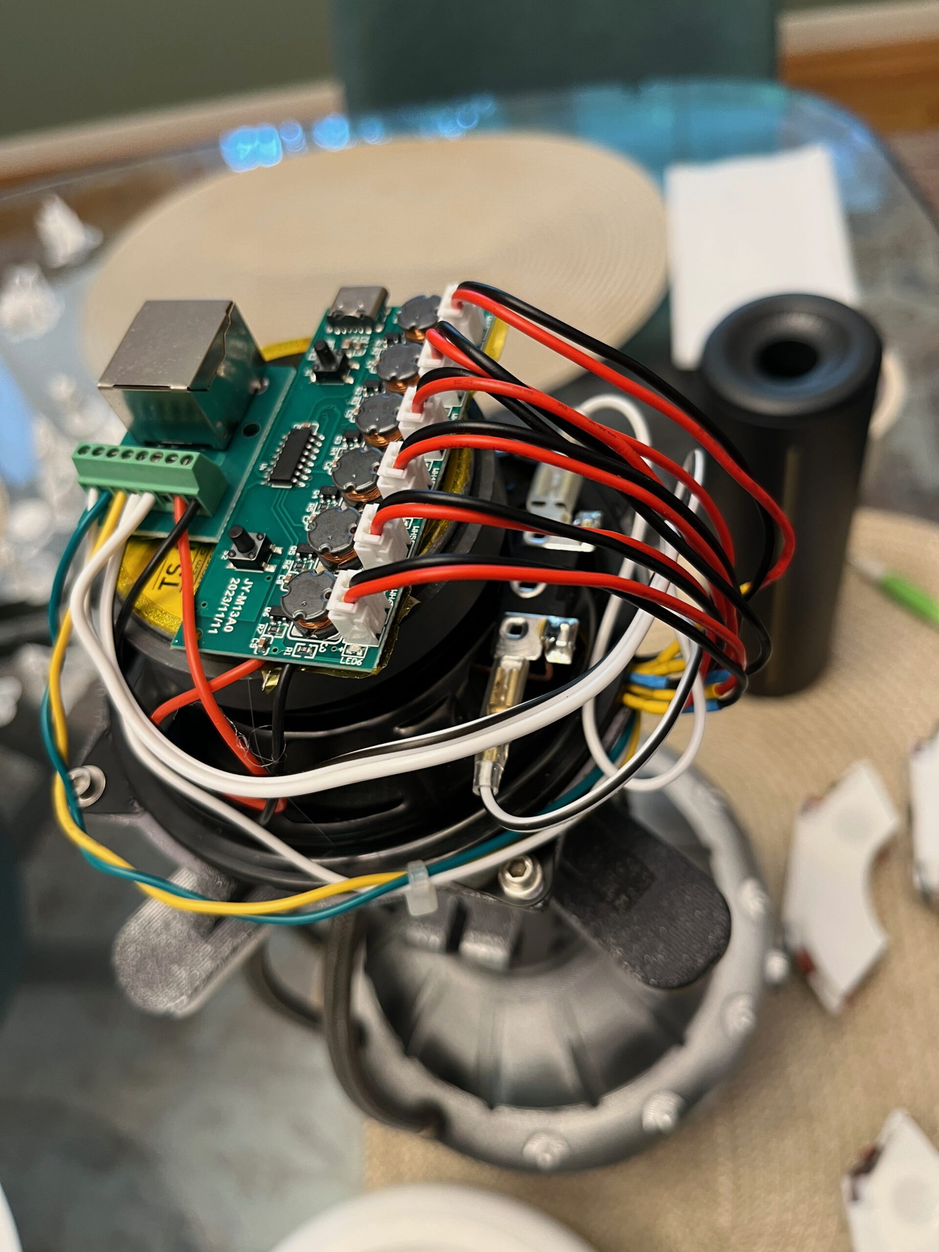
I feel the need to include some photos with this, so here’s a shot of the hardware on top of each engine:
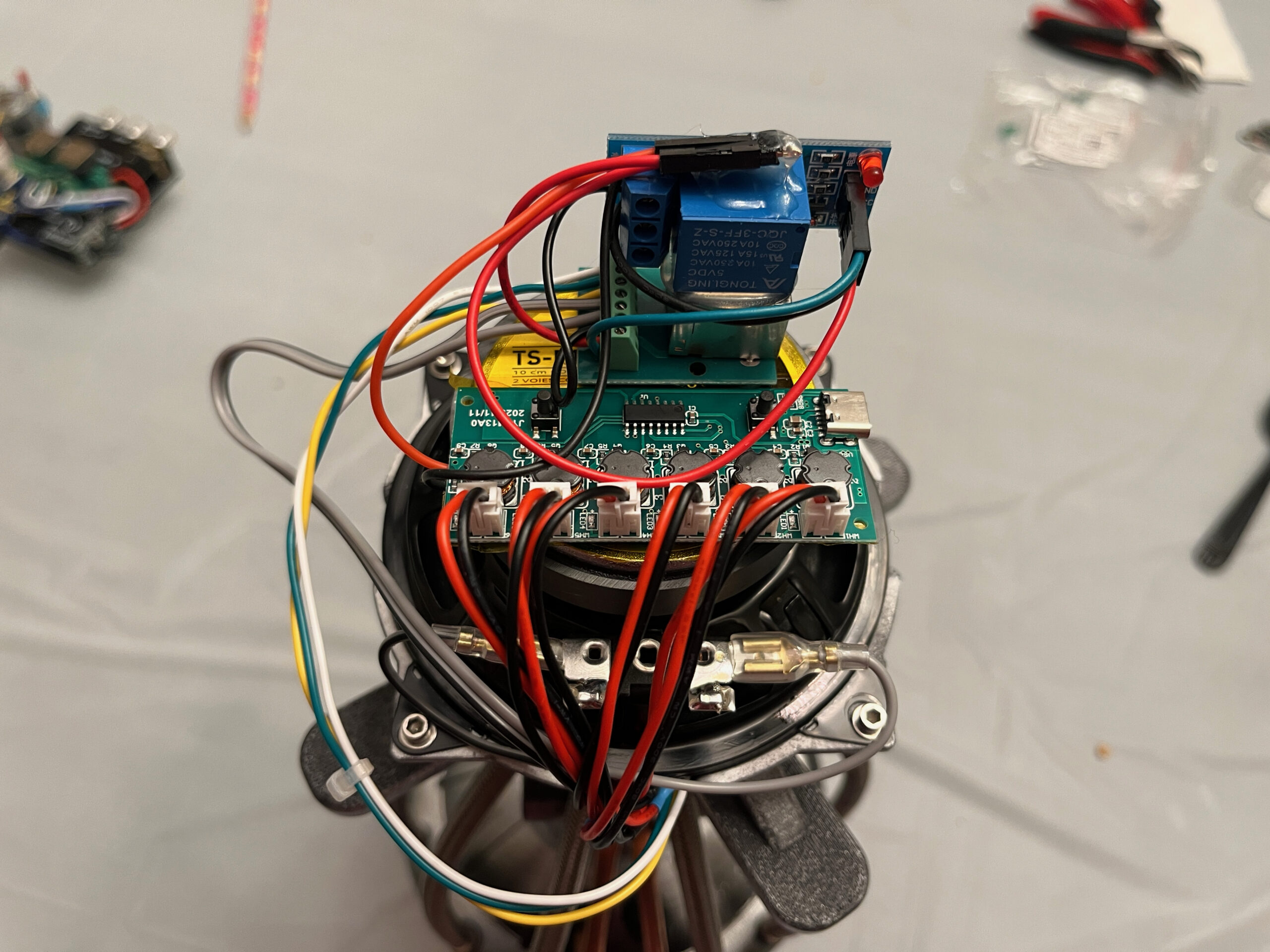
Top to bottom, you can see the relay breakout PCB, then the RJ45 breakout board, then the 6-disc ultrasonic driver board, all mounted on the back of the 4″ speaker.
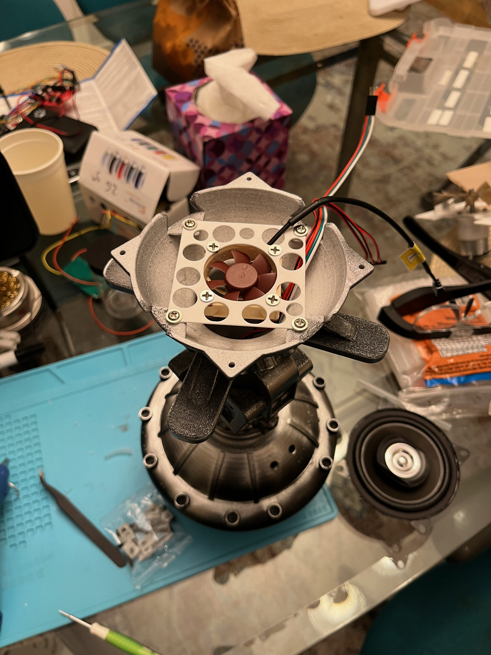
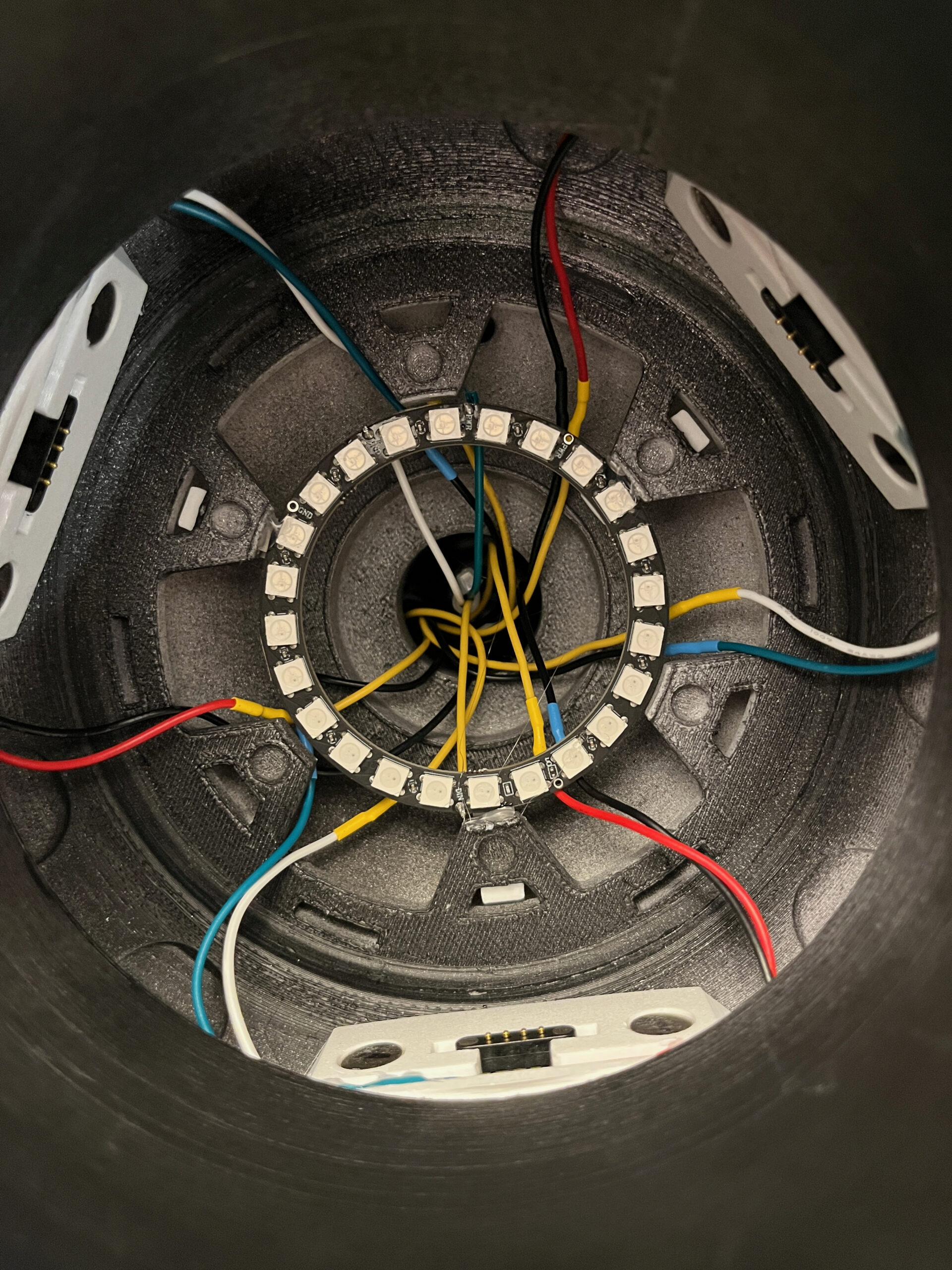
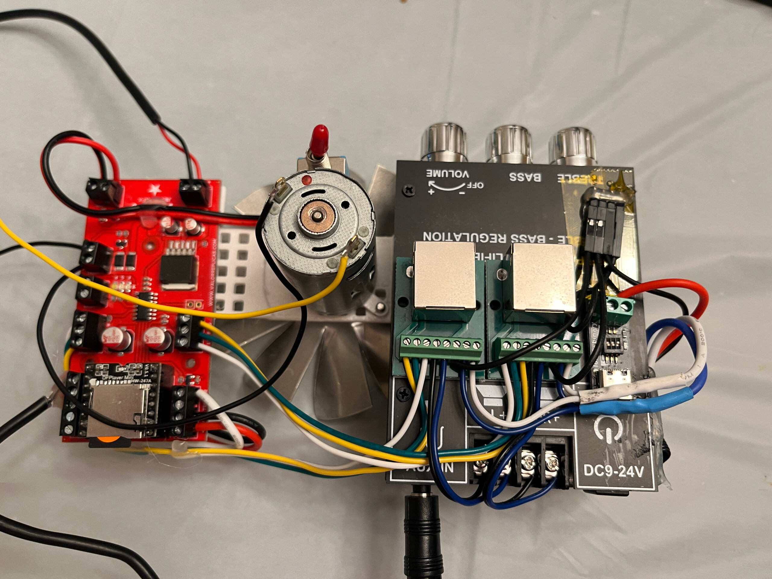
And here’s a view of the central section from above, when the radiator is removed:
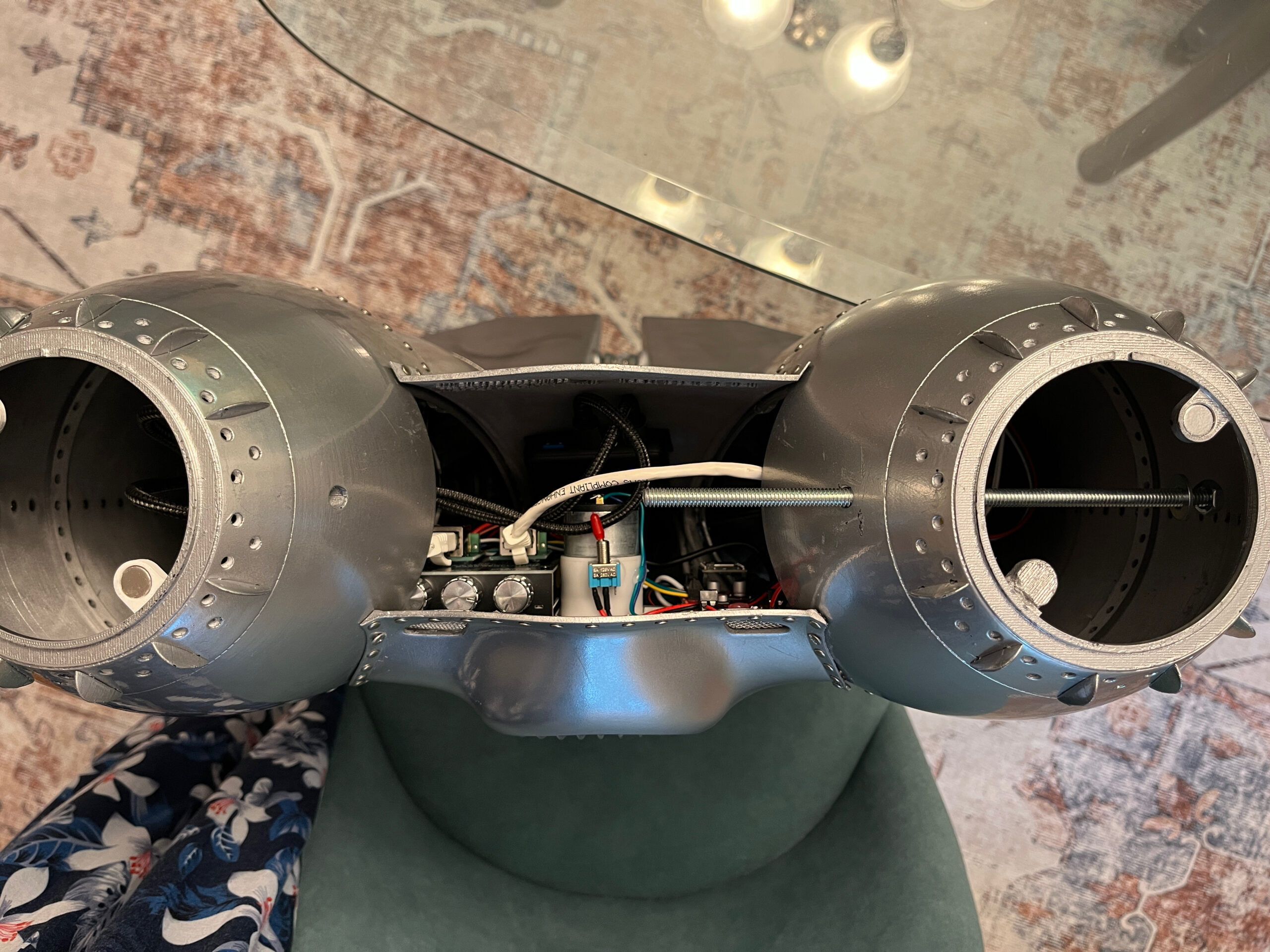
This is without the engines installed, or else you’d see the tops of them in the tanks. In the central section, you can see the audio amp with the RJ45 breakouts on top of it, then the fan motor with power switch, and then the FX board. There’s also a good view of the threaded rod that secures the radiator and holds the top of the tanks in position.